BMW K bikes (Bricks)


You are not connected. Please login or register

View previous topic View next topic Go down  Message [Page 1 of 1]


FreebasserSF

FreebasserSF
Silver member
Silver member
I'm just wondering about some parts on my K100rs. I know that on the rear drive there is some sort of impulse transmitter (which weirdly has only one wire coming from it) and the spinning of the rear wheel produces a square wave which registers on the speedometer. This is the wire I'm talking about:
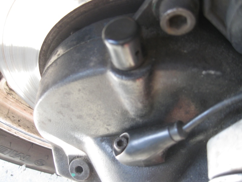
Speedometer, Tachometer, and Cogs near breaks Img_1815

My question is what are the toothed cogs on my front wheel and rear wheel next to the disc brake calipers and attached to the backside of the rotor. Here is what they look like. They seem to have only one wire leading from them and are connect to the caliper by two allen head bolts. On the rear it is:
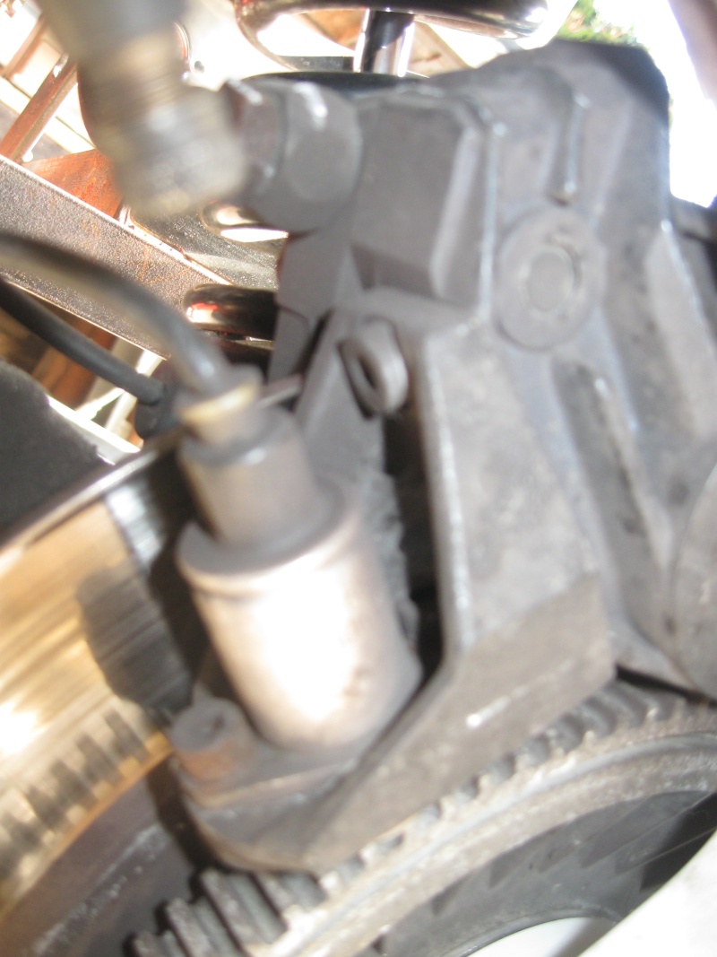
Speedometer, Tachometer, and Cogs near breaks Img_1816

and on the front it is:
Speedometer, Tachometer, and Cogs near breaks Img_1817

I'm sorry if this has been posted or posted about, but I didn't find it when looking, or when looking through my clymer handbook. The cogs themselves on my bike are very rusty and I wondered if this may be contributing to my tachometer and speedometer not working. There is no circuit formed by the sensor (or whatever it is) on the cog and the impulse transmitter right? One last question is what is actually providing the signal to the tachometer?

Thanks for the patience guys.


Toto_jp

avatar
Platinum member
Platinum member
The tooth cog near the brake disk is part of your ABS system as for your gauges not working check all plugs on your electrical wiring Smile


__________________________________________________
K100 RS 1986
    

walfish

walfish
Life time member
Life time member
Freebasser, your first pic shows the final drive with a black unit secured with a cap head screw(allen head)on the final drive, this provides a signal to the tacho. follow the cable you will find a plug near the battery, a common point for bad connection.You will need to clean the contacts there and at the back of the instrument cluster.


FreebasserSF

FreebasserSF
Silver member
Silver member
I've blasted the connections at the back of the instrument cluster with many different solution including Deoxit D series, Deoxit gold, and CVS contact cleaner. I can't guarantee there isn't a bad connection there but I think it could be at some intermediate spot along the signal's path. As a side note, when I first got the bike there was one or two times where suddenly the tachometer started working, but these seemed to be anomalies as they never happened again in the rest of the year and a half I've had this bike.


__________________________________________________
"Build a man a fire and he will be warm for a day. Light a man on fire and he will be warm for the rest of his life."
    

Rick G

Rick G
admin
admin
Lets get all this straight
The gizzmo on the rear drive is the speedo sensor and has 2 wires inside that cable. There is a plug in the circuit which is under the right side cover and may need cleaning with Deoxit but the sensor can be removed by taking out the allen screw and liftimg it straight up (you may need to get a fine screwdriver under it to start it) but clean around it first as grit accumulates there and drops into the drive, wipe the muck of the face of the sensor and replace.
The tacho gets pulses from the second coil to drive it, a blue and black wire.
The toothed cogs are for the ABS wheel sensors (there are 2 wires as for the speedo sensor) and having rust on them could cause a malfunction if the ABS it still operational. The rings can be removed (you may need to heat it) and to remove the rust soak it in molasis at 10-1 mix for a few days then clean of and repaint.
If the tach and speedo are both US then I would suspect the multi pin connector at the rear of the instrument panel, they are noted for giving trouble and may need a good clean and treatment with deoxit. Don't use a dielectric grease or WD40 or similar they are a waste of time and will cause trouble down the track.
That connector has long pins and sometimes the pins need to be twisted or bent very slightly to give a good contact (they're getting old) but only very slight.
Replacing all the fuses is a good idea too, even if they look OK they can give trouble.


__________________________________________________
"Man sacrifices his health in order to make money.
Then he sacrifices money to recuperate his health.
And then he is so anxious about the future that he does not enjoy the present; the result being that he does not live in the present or the future; he lives as if he is never going to die, and then dies having never really lived."   Dalai Lama


Bikes 1999 K1100 LT with a Big Block 1200
    

Inge K.

Inge K.
VIP
VIP
Other known weak connector points in speedometer signal circuit is:

At the bottom of the connector pins at the multiplug connection on the rearside of the instruments.
The pins is pressed/clinched to the plastic frame with the conductive film between.
At this spot a galvanic reaction occurs, due to the different materials.
The reaction got good help to develop from condensation problems in the instruments.
This area get less heat and air to dry up again, with good help from the rubber gasket
to keep the moisture in place.

Another known cause for speedo failure is the three pin connector at the end of the conductive
film which is connected at the top/rear of the speedo.
It`s a piece of rubberfoam on the rearside of this connector, to add a slight pressure to the connector.

Inge K.


FreebasserSF

FreebasserSF
Silver member
Silver member
K Freak wrote:Lets get all this straight

The tacho gets pulses from the second coil to drive it, a blue and black wire.

If the tach and speedo are both US then I would suspect the multi pin connector at the rear of the instrument panel, they are noted for giving trouble and may need a good clean and treatment with deoxit. Don't use a dielectric grease or WD40 or similar they are a waste of time and will cause trouble down the track.
That connector has long pins and sometimes the pins need to be twisted or bent very slightly to give a good contact (they're getting old) but only very slight.
Replacing all the fuses is a good idea too, even if they look OK they can give trouble.

So when you say the tach gets pulses from the second coil do you mean the second wire from the speedo sensor on the rear drive gives it a signal or something else? Also where is a ground in this circuit if there is one?


Inge K.

Inge K.
VIP
VIP
FreebasserSF wrote:So when you say the tach gets pulses from the second coil do you mean the second wire from the speedo sensor on the rear drive gives it a signal or something else?
Tacho gets signal from the second ignition coil.

Both wires from the speedo sensor is connected to the speedo amplifier (in instrument housing.

Inge K.


K-BIKE

avatar
Life time member
Life time member
One problem with our bikes is moisture gets into the instrument cluster and then corrodes the connections inside. The only long term treatment for that is to treat all of the electrical connections in the cluster to the full DeoxIT cleaning regime plug all the circuit boards back together and then seal the cluster as described elsewhere in the article about replacing the instrument lights with LED's.
Regards,
K-BIKE


FreebasserSF

FreebasserSF
Silver member
Silver member
OK so today I've had my speedo apart and I'm just running through all the different circuits and checking for continuity. Just to make sure I'm doing this right, I should measure zero resistance approximately on all connectors, capacitors and other non-resistors correct? Also I looked at the instrument multi-connection plug and it says the tachometer (pin 16) gets grounded by pin 13 and pin 6 but I get no continuity from 16 to 13 or from 16 to 6 while all the other ones do get continuity. Also to Inge K, the 3 prong connecter seems ok but the four prong one was heavily corroded as well as the female part of the connector (green oxidation). Is there any good way to remove those four connectors to clean them? Should I resolder them? And does anyone have a good schematic for how the continuity should be from the 3 prong connector through the speedo motor and to the 4 prong connecter and chip, and to the multi-pin connection?


__________________________________________________
"Build a man a fire and he will be warm for a day. Light a man on fire and he will be warm for the rest of his life."
    

Inge K.

Inge K.
VIP
VIP
Here is diagram for both the amplifier and the speedo board:
(hope the resolution is good enough).

Speedometer, Tachometer, and Cogs near breaks 00210

Speedometer, Tachometer, and Cogs near breaks 00311

Inge K.


FreebasserSF

FreebasserSF
Silver member
Silver member
Thank you Inge. I'm not an electrician so I don't know if I'll be able to make much sense out of it but I'll try and I appreciate it. My main question for you was whether you know a good way to take off the 4 pin connector pins from the speedo (the one that cinches the blue plastic down)? I need to get it off to maybe resolder it and clean it.


__________________________________________________
"Build a man a fire and he will be warm for a day. Light a man on fire and he will be warm for the rest of his life."
    

Inge K.

Inge K.
VIP
VIP
The last post in this thread might help, as connectors is similar.


Clean the area where the pin and conductive film meets, use some fine steel
wool and a pointed instrument first and then some solder flux paste which
you heat a bit with a soldering iron for the the final clean, then wipe of.

If needed use a small sharp knife to remove some plastic (gentle) on the conductive film to get to clean copper (if the surrounding area been corroded away).

Use a small fine pointed soldering iron on this work or you`re in the risk of damaging the conductive film.
Speedometer, Tachometer, and Cogs near breaks 00810

Or solder a thin wire (0,2mm2) between the internal connectors.
Speedometer, Tachometer, and Cogs near breaks Kopi_a10

On other forums and also this one, conductive paint for window demisters
have been suggested for this use, but I haven`t tried that.
(have received expected results with above metods).

Inge K.


Last edited by Inge K. on Sat Feb 18, 2012 2:01 am; edited 6 times in total (Reason for editing : Adding info and pictures.)


charlie99

charlie99
VIP
VIP
yes good suggestion inge ..... that wire you are talking about is often called "mylar wire " cause of the mylar coating ...often used for wire wrapping ....um back in the day .....(can be soldered through verry easily )

the proccess of using mylar wire is to solder both ends to the particular terminals to provide a "bridge " across the now unconductive track ...we usually use a glue ...or nail pollish to fix the mylar wire to the backing so that is dosen't moove ...(cause of vibrations etc ) about every centimeter or 2


there is a product called flux remover which might help with this process ...highly toxic stuff acually ....with carefull application ( cotton bud ) it might help expose the copper tracks or ...at least cleanup the terminals around the solder points ......

just a suggestion ..there is low temperature solder available also ...which would be most advised to use on the film junctions .

the paint on conductive paint ..i had thought to use where there was a slight fracture around the pad of the solder/post point

may i add ...great resources inge .....not only did that circuit have resistor numbers ....but actuall values ...woopee !! mostly we see components in the circuit ..but never values or parts identifiers ...bravo !!

hope this helps someone


View previous topic View next topic Back to top  Message [Page 1 of 1]

Permissions in this forum:
You cannot reply to topics in this forum