1

 Gear selection indicator replacement Wed Mar 01, 2017 4:46 pm
Johnser
Silver member

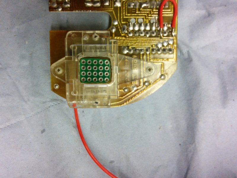
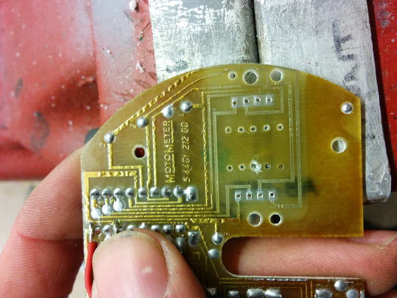
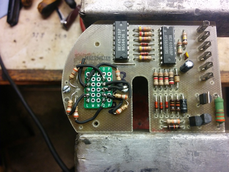
I mentioned in another thread I had been fiddling about trying to get a new LED gear indicator to work. Tonight, it's all come together:
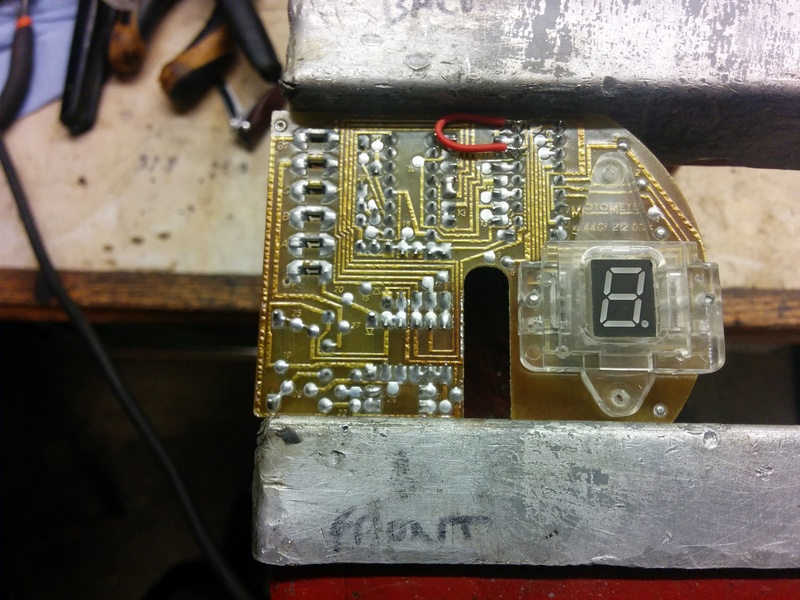
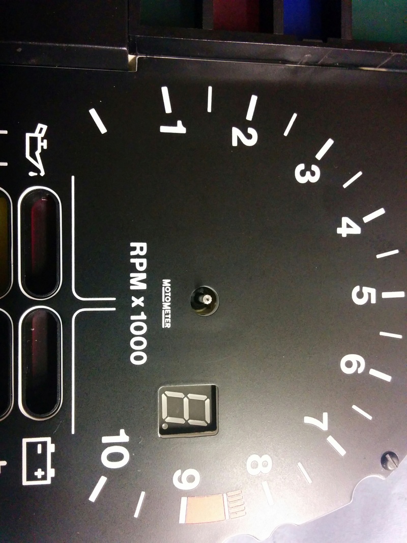
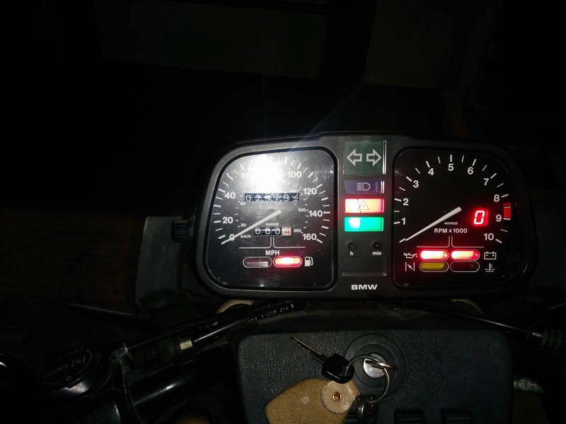
It's not particularly complicated to do but is very fiddly. More than happy with the results though.
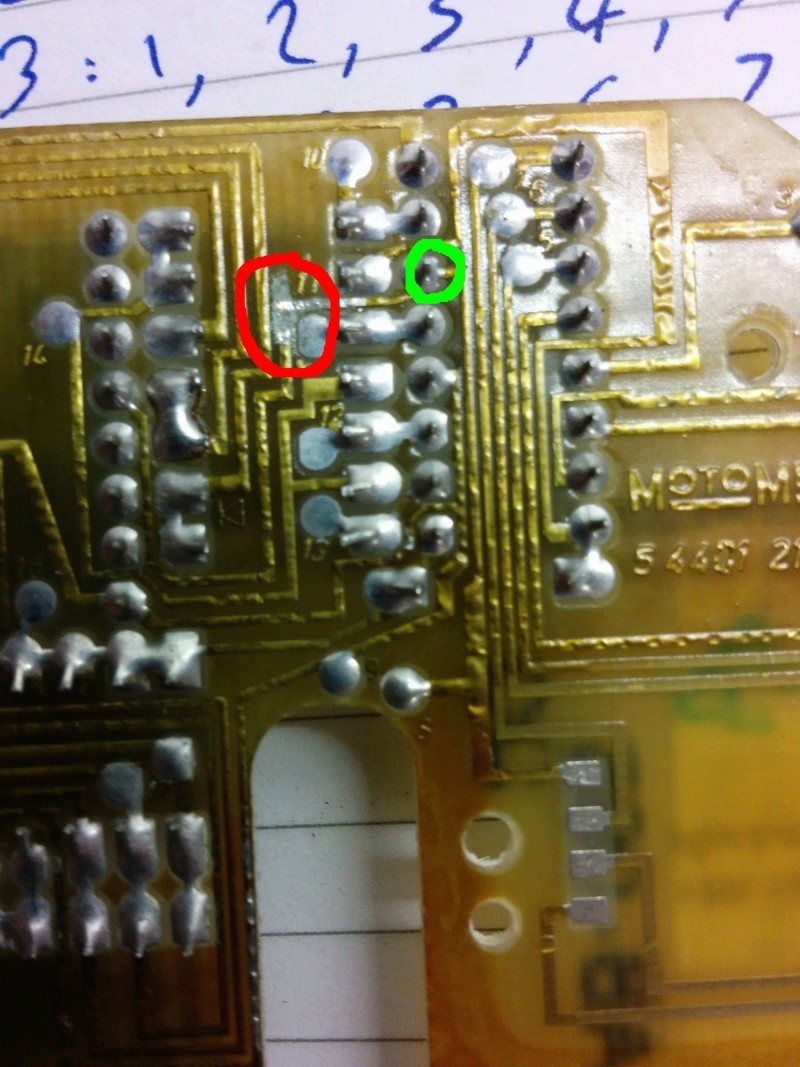
I took a bunch of photos so can put together a bit of a "how to" if anyone's interested. Component cost is tiny but takes a while.


It's not particularly complicated to do but is very fiddly. More than happy with the results though.
I took a bunch of photos so can put together a bit of a "how to" if anyone's interested. Component cost is tiny but takes a while.




 1986 k75, 1985 K100rt,