1

 Aftermarket Gear indicator/Neutral indicator board & 3-circuit Fuse block Thu Sep 04, 2014 8:47 pm
robmack
Life time member

As I have mentioned in previous posts to other discussion threads, I'm designing and building circuits to adapt the K100 electrics to aftermarket gauges.
Gear Indicator and Start Enable Board
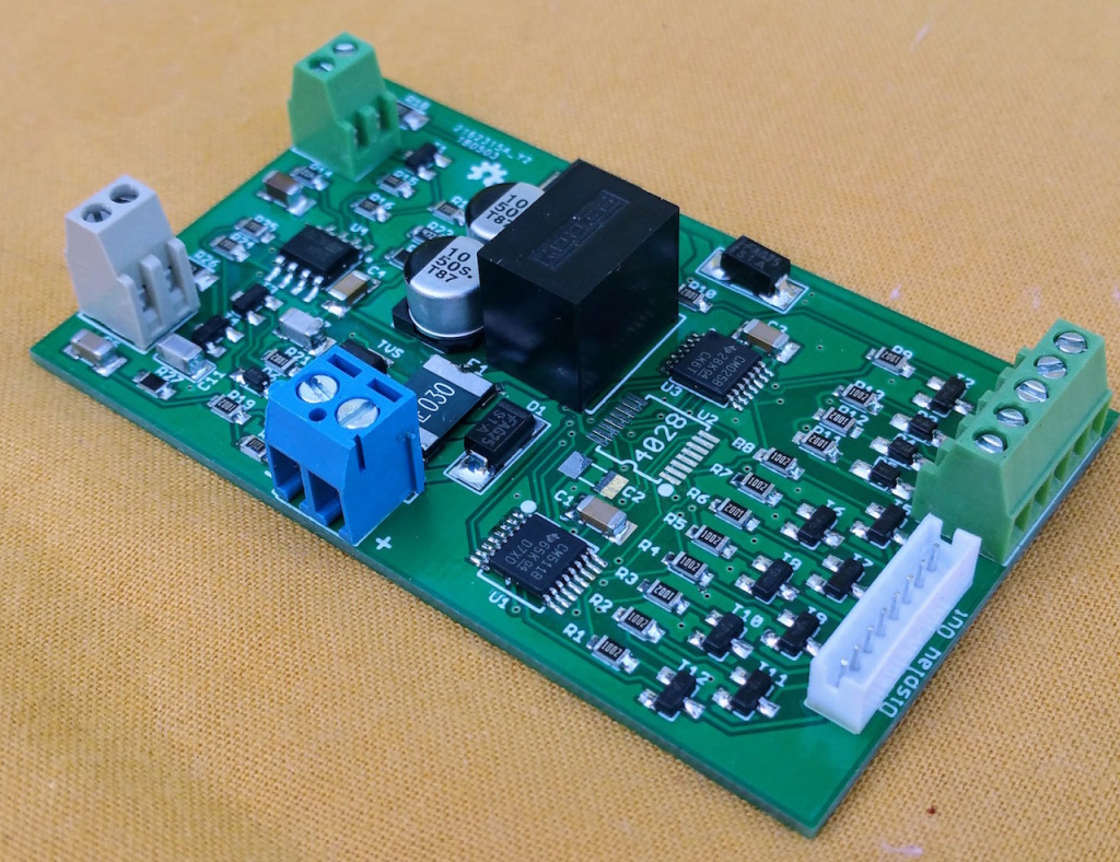
The TGPI design has gone through a few iterations, with the current version 4.1 being based on a micro-sized Arduino processor. This design is adaptable because of the on-board computer and can display the gear in a multiple of ways:
As shown in the photo below, there is a separate 7-segment display board with a cable length of 150mm, however a custom length can be provided if required.. The intention with such a short cable is that the board and display will be together in an enclosure. It is possible that this arrangement does not meet with your intended design. When ordering, I will exchange information with you to understand how and where the board will get use. This allows me to tailor the display umbilical cable to a length that suits your build.
The Gear Indicator and Start Enable Board also has circuitry to amplify and condition the speed signal coming off the rear drive. Many modern aftermarket speedometers require the use of an active inductive sensor that outputs large voltage levels (>7 volts) for the meter to work properly. This usually means adding a magnet and aftermarket sensor to the front wheel to get that signal. The variable reluctance (VR) sensor in the final drive of the K100 is not capable of reproducing these active signals without help. The circuit on this board will amplify the weak VR signal from the K100 sensor, making it usable for a range of aftermarket speedometers. This means one can re-purpose the OEM sensor and avoid adding additional sensors to the bike.. This feature means that you don't have to use the manufacturer's speed sensor and worry about finding a place to mount it.
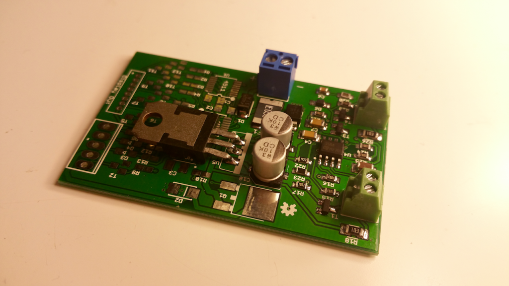
I have developed the next version of the TGPI board (v5.2). This version includes new functionality and a fundamental change in the design. There is a circuit now that will condition the engine RPM signal available on the Black/Blue wire (Pin 16) of the OEM cluster, and make the signal compatible with aftermarket tachometers. I have also included a more robust power supply onboard along with a resettable fuse and transient voltage protection. This will result in a more robust reliable board than previous designs. Finally I have integrated a circuit on the tachometer output that adjusts the signal to make it compatible with one particularly popular Chinese aftermarket gauge.

The overall size of the board is 4cm X 6cm.
The change in design with v5 means that I manufacture the board based on the type of display you desire. There are two versions of the build and unfortunately, they are not interchangeable between themselves. That means we collaborate during the ordering process to make sure I supply you with the correct version of the board.
The tested board and LED display is targeted at $75.00 CDN plus shipping.
TGPI User's Manual Online
Speed and Tachometer Conditioning Circuitry:
If all you're interested in is just the speedometer amplifier circuitry or just the tachometer conditioning circuitry or both, it is possible for me to build only that function on the board and largely ignore the rest of the components. The cost is significantly reduced, down to $25.00 CDN plus postage, for that board.

3 Circuit Switched Fuseblock

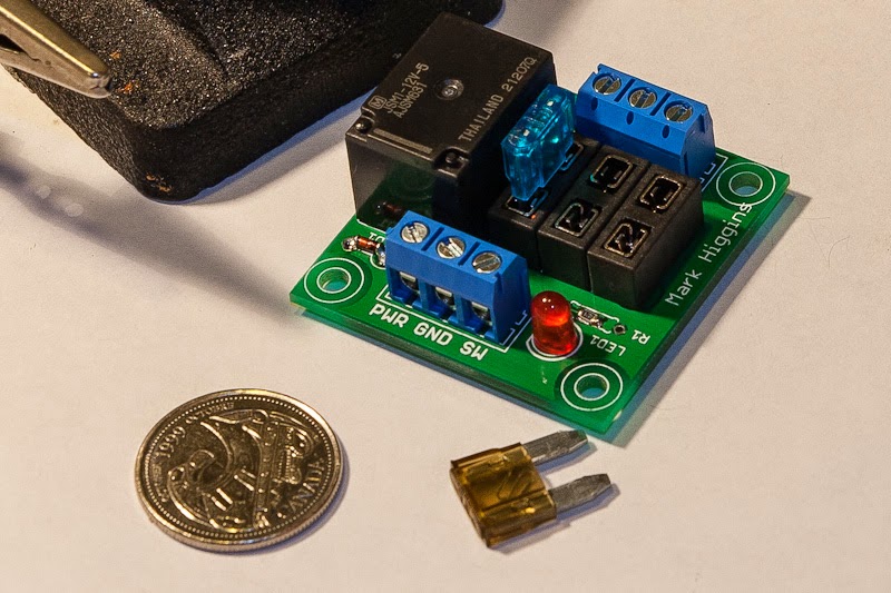
This board provides three switched 12 volt fused circuits in a compact 5cm X 5cm package for powering accessories that you add to your bike. The switching relay is provided on the card, which simplifies the installation. These circuits can handle up to 30A current total (the limit on the switching relay's contacts) and has a LED for power indication. The tested board is $21.00 CDN plus shipping.
The prices are very close to my costs just for the parts that are used. I'm making no money on these, but making them available to support the community of K-bike owners.
4-Relay Neutral Detect:
I have designed a printed circuit board to simplify the construction of the popular neutral detect circuit using four relays. The board using through hole components which should be easy to source locally in a number of markets. I was thinking of supplying this design in a flexible way, to meet different budgets and skill levels.
The board overall is 5cm X 5.2cm in size. It will take input from the TGPI switch and output a Start Enable signal and an active-low Neutral signal whenever the transmission is in neutral position.


Gear Indicator and Start Enable Board
The TGPI design has gone through a few iterations, with the current version 4.1 being based on a micro-sized Arduino processor. This design is adaptable because of the on-board computer and can display the gear in a multiple of ways:
- With a numeric digit using a 7-segment 0.39" LED display[/li]
- With up to 6 LEDs, each LED representing a selected gear[/li]
- With a direct connection to an aftermarket Koso gauge which has inputs for displaying a selected gear[/li]
- With up to 6 incandescent bulbs, similar to the LEDs, but for a retro look when placed behind a bezel[/li]
As shown in the photo below, there is a separate 7-segment display board with a cable length of 150mm, however a custom length can be provided if required.. The intention with such a short cable is that the board and display will be together in an enclosure. It is possible that this arrangement does not meet with your intended design. When ordering, I will exchange information with you to understand how and where the board will get use. This allows me to tailor the display umbilical cable to a length that suits your build.
The Gear Indicator and Start Enable Board also has circuitry to amplify and condition the speed signal coming off the rear drive. Many modern aftermarket speedometers require the use of an active inductive sensor that outputs large voltage levels (>7 volts) for the meter to work properly. This usually means adding a magnet and aftermarket sensor to the front wheel to get that signal. The variable reluctance (VR) sensor in the final drive of the K100 is not capable of reproducing these active signals without help. The circuit on this board will amplify the weak VR signal from the K100 sensor, making it usable for a range of aftermarket speedometers. This means one can re-purpose the OEM sensor and avoid adding additional sensors to the bike.. This feature means that you don't have to use the manufacturer's speed sensor and worry about finding a place to mount it.
I have developed the next version of the TGPI board (v5.2). This version includes new functionality and a fundamental change in the design. There is a circuit now that will condition the engine RPM signal available on the Black/Blue wire (Pin 16) of the OEM cluster, and make the signal compatible with aftermarket tachometers. I have also included a more robust power supply onboard along with a resettable fuse and transient voltage protection. This will result in a more robust reliable board than previous designs. Finally I have integrated a circuit on the tachometer output that adjusts the signal to make it compatible with one particularly popular Chinese aftermarket gauge.

The overall size of the board is 4cm X 6cm.
The change in design with v5 means that I manufacture the board based on the type of display you desire. There are two versions of the build and unfortunately, they are not interchangeable between themselves. That means we collaborate during the ordering process to make sure I supply you with the correct version of the board.
The tested board and LED display is targeted at $75.00 CDN plus shipping.
TGPI User's Manual Online
Speed and Tachometer Conditioning Circuitry:
If all you're interested in is just the speedometer amplifier circuitry or just the tachometer conditioning circuitry or both, it is possible for me to build only that function on the board and largely ignore the rest of the components. The cost is significantly reduced, down to $25.00 CDN plus postage, for that board.

3 Circuit Switched Fuseblock

This board provides three switched 12 volt fused circuits in a compact 5cm X 5cm package for powering accessories that you add to your bike. The switching relay is provided on the card, which simplifies the installation. These circuits can handle up to 30A current total (the limit on the switching relay's contacts) and has a LED for power indication. The tested board is $21.00 CDN plus shipping.
The prices are very close to my costs just for the parts that are used. I'm making no money on these, but making them available to support the community of K-bike owners.
4-Relay Neutral Detect:
I have designed a printed circuit board to simplify the construction of the popular neutral detect circuit using four relays. The board using through hole components which should be easy to source locally in a number of markets. I was thinking of supplying this design in a flexible way, to meet different budgets and skill levels.
- A completely assembled and tested circuit (first photo)[/li]
- A kit consisting of the PCB and all parts ready to be assembled (second photo)[/li]
- The raw PCB[/li]
The board overall is 5cm X 5.2cm in size. It will take input from the TGPI switch and output a Start Enable signal and an active-low Neutral signal whenever the transmission is in neutral position.
Last edited by robmack on Sat Jun 02, 2018 6:31 pm; edited 14 times in total
__________________________________________________
Robert
1987 K75 @k75retro.blogspot.ca


