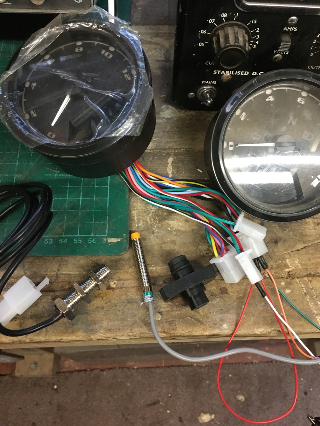
Well, seeing as I'd ordered a small bucketful of capacitors and transistors and...stuff, I thought I might just as well explore Plan A and come up with a diy circuit to obviate any more thefts of the OE speedometer boards (Things To Do In Lockdown When You're Bored, remember)
And...seeing as my new oscilloscope needed an outing ('new' = 40 years old, compared to its predecessor which was 50+ and recently died

)
...I set about this circuitry lark, with zero expectations of success, armed with a couple of speculative diagrams courtesy of the interweb. Turns out I was overestimating things. All it takes to get the OE speedometer sender to drive the Oohbay instruments of doom, is this:

Which costs an eye-watering thirtyone pee, or five for one pound fiftyfour pence (one to use, one to lose, and three to flick at your friends). Nothing else required (apart from a socket and a little bit of veroboard I suppose).
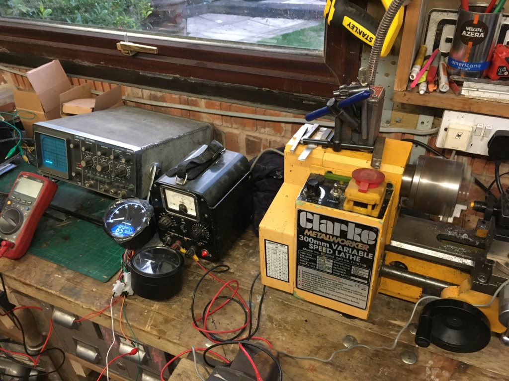
I set off with a breadboard full of, things, mostly randomly connected as is my style. And the thing worked (OE speed sensor clamped in the lathe, again, and a spare set of instruments rolling about the bench with the vibration) One by one I took out the various clamping resistors (who needs 'em) the capacitors (don't understand what they do anyway), and finally, the diode (probs because I've never sussed whether the little painted ring at one end means positive or...the other one). Everything carried on working, which is maybe because the instruments have a reasonable (i.e bombproof) circuit for the input.
Here's the proof. Little mister thirtyone pee is the tiny thing in the middle:

Here's the not very technical (or accurate) explanation:

The above trace is just the raw output from the OE sender - the raw voltage it generates as the toothed ring whizzes past. It's about 2 volts peak to peak, gets a bit higher if you open the taps, drops to about 1 volt peak to peak at walking pace, but mostly its about 2 volts.
The OE speedometer circuit board takes this raw signal and does (I guess) a top-quality job of smartening this up into a BMW-quality output that is good enough to go into the fine, old, analogue speedometer.
You don't need this quality of work for those cheapo Oohbay instruments, so leave that circuit board alone, do you hear!All you need is mister thirtyone pee. Here's what that little fellow can do:

The top trace is the output from the OE sender (okay the bottom bit of the wave is a little bit clipped off, but that's because it's now connected to one of thirtyone pee's legs). The bottom trace is the output from thirtyone pee. Which is a nice clean 12volts, dropping (nice and cleanly) to 0volts everytime the sender coughs. This output from thirtyone pee drives the Oohbay instruments just fine -at walking pace, at GLF, and everything inbetween. (Tested for fifteen minutes or so until the plastic change gears on the lathe melted a bit - forgot to put the leadscrew into neutral, oh well, eggs and omelettes and all that)
I did precede this with a circuit that cleaned up the OE sender output a bit (top trace shown below) but this bit of refinement wasn't necessary in the end - mister thirtyone pee can sort all that out.

The above pic also shows that inverting the input to the instruments isn't necessary either, all it needs to see is a drop from 12v to 0v somewhere along the line (hah, 'inverting the input', I mean swapping the sender output to a different one of thirtyone pee's legs, sorry)
The supply voltage for this was coming from a nearly-prehistoric power supply (on the back there's a sticker with a scribbled diagram showing how to attach the crocodile clips to the 'bolts though the neck' or something) I'd like to bet it can teach a motorbike about messy spikes and crap. So, I'm confident that this will work on the actual bike.


 WTB Speedometer Circuit Board. Tue Mar 31, 2020 12:25 am


 [url=https://servimg.com/view/19946756/17]


 1984 BMW k100..frame number 6228?
