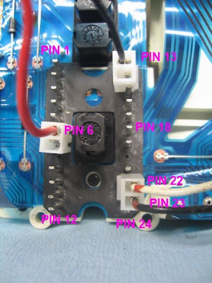
K Freak wrote:These are the pin allocation on the back of the speedo those in red are the ones you can use for a bench run, I am not sure which brown earth wire is relevant so connect both
Use pin 13 for the speedo testing and calibration. The other ground is for lighting.
Here is additional text that I added to my Karamba User's Guide (but haven't uploaded yet; too busy with work and a three year old tornado, A.K.A. my son.
Cable Hookup
To bench test, the instrument cluster must be supplied +12 volt DC from an external source such as a battery or power supply. In addition, provision must be made to hook up proper signals to the transducer inputs on the cluster.
The power supply cable is very simple. I used alligator clips attached to wires that terminated in 2-terminal Molex header connectors with 0.156” pins. This particular header connector has the correct pin spacing for the instrument cluster. The reason I used 2-terminal Molex connectors instead of 1-terminal was to ensure that the connections were oriented properly. Crimp Molex terminals on one end of the wire and insert into one of the shell’s holes (doesn’t matter which one). Solder an alligator clip onto the other end of the wire. Repeat for a second wire.
Similarly, manufacture a signal cable using the instructions provided earlier in this document however, instead of using ¼” spade connectors, use a 2-terminal Molex connector.
1. Connect the power and signal cables to the main header connector back of the instrument cluster in the following way:
• +12VDC is connected to Pin 6
• Power ground is connected to Pin 13
• Signal+ is connected to Pin 22
• Signal- is connected to Pin 23
You can see the proper connections in the photo

2. Connect the 3.5mm stereo plug to the laptop. Connect +12V to the positive of a power source; connect Ground to the negative of a power source
3. Run the Karamba program.
Hint
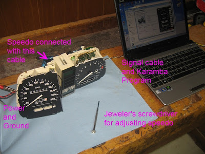
Normally, one disconnects the speedometer subassembly to provide maximum access to the adjustment potentiometer. I have found that it is possible to orient the speedometer subassembly without disconnecting it in order to adjust the potentiometer while the Karamba program is running. This greatly speeds the process of adjusting the speedometer’s precision. Remove the speedometer sub-assembly from the instrument cluster as described above. Reconnect the 4-pin header and flexible circuit card that attached the speedometer sub-assembly to the main circuitry. Be careful not to kink or stretch the flexible circuit card as it could damage the copper traces. The only caution to take is to be careful when inserting the jeweler’s screwdriver into the innards of the speedometer sub-assembly to make sure you don’t accidently short out electronics. You can adjust the pot and watch its response on the display realtime. The process of converging the speedometer’s reading is reduced to just a few seconds because you get instant feedback how your adjustment is affecting the needle.

The image above shows the orientation of the speedo that just offers enough room to access the adjustment pot while still allowing the flexi-cables to be connected yet not stressing them.


 Speedo defecit Sun Nov 13, 2011 2:44 pm


