BMW K bikes (Bricks)


You are not connected. Please login or register

View previous topic View next topic Go down  Message [Page 1 of 1]


1Back to top Go down   Speedo Wiring Help In Colorado? Empty Speedo Wiring Help In Colorado? Tue Aug 07, 2018 3:02 pm

Hale_Storm

Hale_Storm
active member
active member
Anyone on the site live in the Colorado area and have any experience with wiring an aftermarket Speedometer?

I bought one of the knock off digital tach/speedos and cannot get it to power up. I suspect its a faulty unit, but i'm not 100% sure, i'm fairly illiterate when it comes to wiring diagrams and such.


Last edited by Hale_Storm on Tue Aug 07, 2018 4:26 pm; edited 1 time in total


2Back to top Go down   Speedo Wiring Help In Colorado? Empty Re: Speedo Wiring Help In Colorado? Tue Aug 07, 2018 3:07 pm

Hale_Storm

Hale_Storm
active member
active member
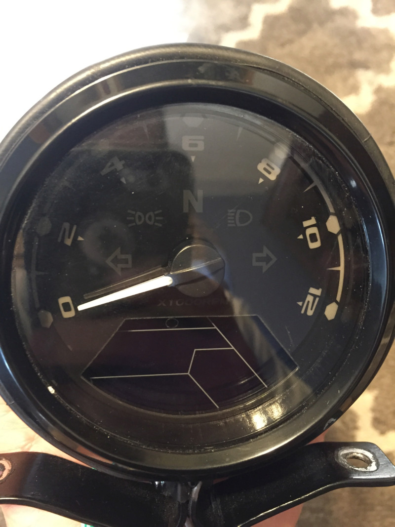
Speedo Wiring Help In Colorado? 15336610
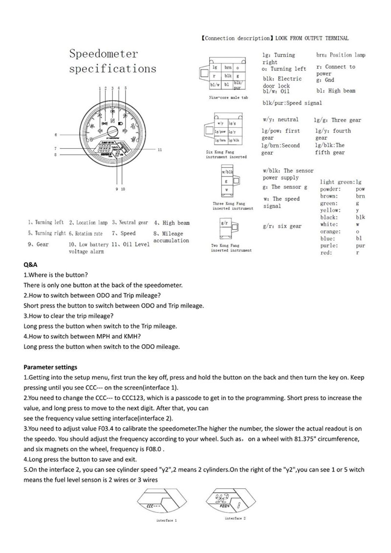
Speedo Wiring Help In Colorado? 15336611
Speedo Wiring Help In Colorado? 15336612

This is what I have/the wiring diagram

Sent from Topic'it App


3Back to top Go down   Speedo Wiring Help In Colorado? Empty Re: Speedo Wiring Help In Colorado? Tue Aug 07, 2018 11:30 pm

robmack

robmack
Life time member
Life time member
I wrote this document if you haven't yet seen it  Speedo Wiring Help In Colorado? 78846 :

https://drive.google.com/open?id=15CRrZ74KuwMdrZ1FZhfTuxBguhFVAXQF

If it doesn't power up, then you're probably not supplying BOTH power leads.  These would be Red (Connect to Power), and  Black (Electric Door Lock).  Don't worry, everyone overlooks connecting up their BMW K100 electric door locks for some strange reason!  Speedo Wiring Help In Colorado? 44271 . Ground is Brown (Gnd).  In my document, I think you have Version 3 wiring.


__________________________________________________
Robert
1987 K75 @k75retro.blogspot.ca
http://k75retro.blogspot.ca/
    

4Back to top Go down   Speedo Wiring Help In Colorado? Empty Re: Speedo Wiring Help In Colorado? Wed Aug 08, 2018 7:54 pm

D'Ecosse

D'Ecosse
active member
active member
Ground is Green 
And yes, you will need both red to constant power and black to switched power


5Back to top Go down   Speedo Wiring Help In Colorado? Empty Re: Speedo Wiring Help In Colorado? Wed Aug 08, 2018 8:08 pm

D'Ecosse

D'Ecosse
active member
active member
robmack wrote:I wrote this document if you haven't yet seen it  Speedo Wiring Help In Colorado? 78846 :

https://drive.google.com/open?id=15CRrZ74KuwMdrZ1FZhfTuxBguhFVAXQF ....

Respectfully have to disagree with the # Cylinders programming
Whether a K100 or K75 both have wasted spark and fire on every TDC. 
These are for different reasons but the result is the same - the K100 has shared coils, so fires two cylinders at same time; one is wasted the other is true firing spark; on next rotation they fire again, but of course the opposite cylinder is igniting this time. 
The K75 has one dedicated coil to each cylinder however the trigger fires on every TDC. So also has wasted spark. 
The number of cylinders is irrelevant - those inputs are holdovers for old-school distributors where there would be multiple sparks generated by the coil for every cylinder in a single revolution; (or if you were looking at the composite trigger signal); in this application it is only looking at only a single cylinder drive so what the other cylinders are doing (or how many there are) is irrelevant. 
Taking Cylinder 1 as the applicable signal, that will have a pulse on EVERY 360 rotation of the crank.


6Back to top Go down   Speedo Wiring Help In Colorado? Empty Re: Speedo Wiring Help In Colorado? Wed Aug 08, 2018 10:11 pm

robmack

robmack
Life time member
Life time member
Thanks for the explanation, D'Ecosse, but I'm not sure then what reason the manufacturer allows three different variables to be set for that configuration option if the number of cylinders don't matter. For a K75 or K100, this motorcycle gauge should be programmed for "1" cylinder then?? Guess I'm confused.


__________________________________________________
Robert
1987 K75 @k75retro.blogspot.ca
http://k75retro.blogspot.ca/
    

7Back to top Go down   Speedo Wiring Help In Colorado? Empty Re: Speedo Wiring Help In Colorado? Wed Aug 08, 2018 11:24 pm

D'Ecosse

D'Ecosse
active member
active member
I think those settings are just holdovers from old-school applications - if the trigger wheel had a trigger for every cylinder's TDC position (and it was sensing directly off that trigger pulse rather than the coil drive pulse) or if there was a distributor in effect, the signal would have a pulse at every cylinder's TDC (or every other TDC) so the count would have to be divided by # of cylinders in that case. 
However it will be rare these days and most applications (anything within at least last 20 years for most part) will be detecting at the coil (or the equivalent in a direct output for OEM tach from the ECU) at either one pulse per revolution (wasted spark or 2-stroke) or one pulse every other revolution for non-wasted spark 4-stroke (in which case the resultant rpm is actually twice that of the detected frequency of pulses).
Most bikes are simply going to look at the signal to one coil - which is effectively the same as if it was single cylinder bike (only caveat being if it was indeed a wasted spark system). 
So for coil signal system either 1 pulse 1 revolution or 1 pulse 2 revolutions are going to be the common settings - and indeed on the K bikes it is going to be 1/1 for both 3 & 4 cylinders. 
Note that most 4-strokes will typically mark the TDC for cylinder #1 and since that is on the Crank, will be on every revolution. And then the ECU will determine the timing and on which cycle to fire if NOT wasted spark. 
Consider a fictional 3 cylinder machine that has a trigger wheel that detects the TDC of EACH of the three TDC events (one for each cylinder); 
if you were to look at that Trigger detector (crank position sensor), then you would have three pulses for every revolution. So if using this signal for the tach, you would indeed have to divide by three.
But on same bike, with three separate coils, the ECU will decode that signal and ONLY send the reference from the appropriate TDC to the appropriate coil i.e. the coil for say cyl 1 does not see pulses when the other two cyls are at their own TDC. So if you detect the coil signal, it really is detecting only one pulse per engine revolution (although on some bikes the ECU may also have timed it down to only a pulse on the firing stroke when NOT wasted spark). 
'Most' ECU and CPS will only mark the #1 TDC and the ECU computes the timing for the other cylinders. 

This is getting off-subject a bit, but you may find this interesting - 
so generally the ECU does not know from the Crank Position Sensor alone, whether each TDC is at top of compression stroke or exhaust stroke; (on the BMW K's, it actually doesn't matter or 'need' to know);
On many cars (& some bikes) they determine the firing cycle by also looking a CAM position sensor, so can tell from that which cycle is on; 
on First generation Triumph EFI (1997) they utilized a French Sagem ECU - this was actually pretty sophisticated in how it determined the cycle; 
no Cam sensor! But the Crank Position sensor not only has the TDC trigger (longer tooth), there are also evenly spaced teeth all around the trigger wheel that also feed pulses to the ECU and it computes the relatively minute difference in rate of change of speed (aka acceleration) and so can tell which is the power stroke! 
The next generation of bikes used Keihin ECU and these do not have a cam sensor either - these have a MAP sensor which measures pressure in the intake (throttle body below the throttle plate) - it again detect the difference in pressure (vacuum) on the intake stroke so uses that to determine the correct cylinder timing. It's actually again very sophisticated in that although there is only ONE common MAP sensor (with a 3-way TEE connecting to the three TB's) the ECU knows which intake pressure relates to which cylinder as it is timed in relation to  the Crank Position Sensor (the low pressure reading following #1 TDC MUST be the intake stroke for that cylinder; following the next #1 TDC 360 crank deg later, it will not have a low pressure following that position on that stroke)  
All very clever stuff! 

Sorry for distraction - normal programming will now be resumed Very Happy

And again in summary, treat the K bike like a single cylinder 2-stroke as far as the Tach signal goes  Very Happy


8Back to top Go down   Speedo Wiring Help In Colorado? Empty Re: Speedo Wiring Help In Colorado? Thu Aug 09, 2018 6:24 am

Dai

Dai
Life time member
Life time member
Nice info! Yes, I did find it interesting! Very Happy


__________________________________________________
1983 K100 naked upgraded to K100LT spec after spending time as an RS and an RT
1987 K100RT
Others...
1978 Moto Guzzi 850-T3, 1979 Moto Guzzi 850-T3 California,1993 Moto Guzzi 1100ie California
2020 Royal Enfield Bullet 500
    

9Back to top Go down   Speedo Wiring Help In Colorado? Empty Re: Speedo Wiring Help In Colorado? Thu Aug 09, 2018 7:55 am

robmack

robmack
Life time member
Life time member
I, like Dai, found this very interesting. The question of what value to set for this variable in this gauge has cropped up on this board a few times. No one was sure how to set it for the K75, since there was no "3" value from which to choose. You state it quite clearly that the correct value for all classic K's is "1".


__________________________________________________
Robert
1987 K75 @k75retro.blogspot.ca
http://k75retro.blogspot.ca/
    

10Back to top Go down   Speedo Wiring Help In Colorado? Empty Re: Speedo Wiring Help In Colorado? Thu Aug 09, 2018 1:09 pm

Hale_Storm

Hale_Storm
active member
active member
alright... you guys lost me...

so back to the power, I got the unit to power up, I connected power to both the R pin on the 9 pin connector and the w/ Blk pin on the 3 pin connector, and brown/negative to both the G ground connectors, but the back light is not showing up? is there another pin that requires power to light up the unit? is that the black door lock connection you mentioned?


11Back to top Go down   Speedo Wiring Help In Colorado? Empty Re: Speedo Wiring Help In Colorado? Thu Aug 09, 2018 1:46 pm

Hale_Storm

Hale_Storm
active member
active member
robmack wrote:I wrote this document if you haven't yet seen it  Speedo Wiring Help In Colorado? 78846 :

https://drive.google.com/open?id=15CRrZ74KuwMdrZ1FZhfTuxBguhFVAXQF

If it doesn't power up, then you're probably not supplying BOTH power leads.  These would be Red (Connect to Power), and  Black (Electric Door Lock).  Don't worry, everyone overlooks connecting up their BMW K100 electric door locks for some strange reason!  Speedo Wiring Help In Colorado? 44271 . Ground is Brown (Gnd).  In my document, I think you have Version 3 wiring.

I did buy your TGPI board about 5 months ago, give or take. I've only just wired it up, but was waiting to figure out this Speedo/Tach. I did have a question on which wire goes to the Neutral connection on the board? I get lost quick when reading technical electrical documents... everything else was super clear, and had color coded wires from the BMW to your unit, but that one confused me a bit...


12Back to top Go down   Speedo Wiring Help In Colorado? Empty Re: Speedo Wiring Help In Colorado? Thu Aug 09, 2018 1:50 pm

D'Ecosse

D'Ecosse
active member
active member
I was actually initially doubtful myself about the wasted spark on the K75 - it would not be typical on a bike with individual coils - although it's certainly simpler to do that than determine the correct firing stroke. About the only down side is spark plug life.

A local very knowledgeable K75 aficionado (he has about 5 of them!) had told the bike's owner (not to me directly) it was and I was skeptical - So I researched it and indeed found it to be the case

Actually that same local expert I discovered posted that info here - https://forums.bmwmoa.org/showthread.php?80736-Why-two-Hall-sensors-on-a-K75

One (sensor) fires one cylinder,the second fires another, and the ignition box uses the two signals to calculate the third. It's a wasted spark system, so each cylinder fires once per revolution, not every other revolution on the compression stroke.

It is corroborated here - http://www.oocities.org/fwarner_au/mc_things/efiithoughts.html


]The current ignition system uses the engine position sensors (2off, one at TDC cylinder 1, the other TDC cylinder 2) to calculate engine speed (period), the third cylinders TDC point and from this the ignition point of each cylinder. The sensor shield has 2 gaps - this can be used to find TDC of cylinder 3. 
There is no TPS, vacuum advance ... just the equivalent of the old mechanical advance. The system does drive the 3 coils directly and has a wasted spark as the engine position sensors are on the crank shaft so the system cannot tell if this is a power stroke or an exhaust stroke

Of course all of that just validates that there is indeed wasted spark on K75 - the # of cylinders not being a factor in the individual coil drive signal is somewhat intuitive (it only contains a drive signal to fire the coil for that cylinder alone)

Apologies again to the OP - asked a simple question about powering up & got a whole lot more than maybe wanted! Very Happy


13Back to top Go down   Speedo Wiring Help In Colorado? Empty Re: Speedo Wiring Help In Colorado? Thu Aug 09, 2018 1:55 pm

D'Ecosse

D'Ecosse
active member
active member
Hale_Storm wrote:... I did have a question on which wire goes to the Neutral connection on the board? ...

The White/Yellow from your instrument will go to the Neutral Output from the TGPI

Not to the instrument of course but you should also wire the start enable output from the TGPI - that would be the OEM Black/Green


14Back to top Go down   Speedo Wiring Help In Colorado? Empty Re: Speedo Wiring Help In Colorado? Thu Aug 09, 2018 7:15 pm

D'Ecosse

D'Ecosse
active member
active member
Does your K100 Fuel tank have the actual Resistive Fuel LEVEL Gauge or Thermistor low-level trigger sensors?
If the former you can use the Fuel Level gauge in the instrument you bought
I have some notes on that in my Acewell 2853 observations thread (but moot if you don't have the resistor level gauge in your tank)

Note that the Chinglish says Oil Level! This is the Fuel Level bar gauge!
(annoyingly there is no warning light or input for the Low Oil Pressure on these units)
You might consider some auxiliary LEDs for Low Oil Pressure and Coolant Overtemp

Another factor to take into account is the Charge Connection for the Alternator Field Coil (this is the OEM Blue Wire that went to instruments)
Connect a 47/50 ohm 5W resistor between Ignition Power (Green/Black) and the Blue wire.

Use something like this device if you want a voltage status indicator - http://www.sparkbright.co.uk/sparkbright-eclipse-battery-voltage-monitor.php
^ He does offer custom thresholds at no extra charge (no pun intended!) - for the BMW I would suggest reducing the 'normal' running voltage threshold to 13V rather than his std 13,2V - the Alternator does not do much more than this so it it would be more useful as indicator to have it trigger at 13.0V (it will still comfortably let you know if you have a problem)


15Back to top Go down   Speedo Wiring Help In Colorado? Empty Re: Speedo Wiring Help In Colorado? Mon Aug 13, 2018 12:06 pm

Hale_Storm

Hale_Storm
active member
active member
D'Ecosse wrote:Does your K100 Fuel tank have the actual Resistive Fuel LEVEL Gauge or Thermistor low-level trigger sensors?
If the former you can use the Fuel Level gauge in the instrument you bought
I have some notes on that in my Acewell 2853 observations thread (but moot if you don't have the resistor level gauge in your tank)

My bike is an 85, so i do not have the float style fuel gauge, i have one that looks like this:

https://www.beemerboneyard.com/kfask10085flsend.html

Not sure if its possible to get that to work with the fuel level indicator? the wiring diagram for the speedo only has one wire for "Oil" shown, not sure if thats an oil light, or the fuel level...


16Back to top Go down   Speedo Wiring Help In Colorado? Empty Re: Speedo Wiring Help In Colorado? Mon Aug 13, 2018 12:29 pm

Hale_Storm

Hale_Storm
active member
active member
Sorry for my electrical ignorance, i am riding the struggle bus through hooking this thing up...

I was able to power up the unit and get the back light going by wiring everything up with power straight from the battery. However when connecting everything up to the instrument wiring, i get no power... I tested the the voltage at the fuses and there is nothing at the fuses... so i know im not getting power there, but i'm not quite sure where to chase it from there.

I did blow the fuse wiring up the brake light the other day, and now my brake light is not working. the tail light and turn signals work, but not the brake.

Given those two items, any suggestions on what might be the culprit?


17Back to top Go down   Speedo Wiring Help In Colorado? Empty Re: Speedo Wiring Help In Colorado? Mon Aug 13, 2018 2:24 pm

D'Ecosse

D'Ecosse
active member
active member
[quote="Hale_Storm"]
D'Ecosse wrote:... Not sure if its possible to get that to work with the fuel level indicator? the wiring diagram for the speedo only has one wire for "Oil" shown, not sure if thats an oil light, or the fuel level...

The input is definitely Fuel LEVEL not oil.

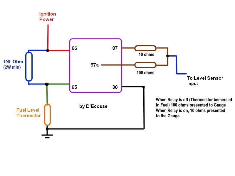
Since you have thermistor, you can do something like this

Speedo Wiring Help In Colorado? Fuel_l11

That will give you a full and empty 'level' on the bar gauge.
(You just need to pick whichever of the two sensors you want to be the trigger level)

Hale_Storm wrote:I did blow the fuse wiring up the brake light the other day, and now my brake light is not working. the tail light and turn signals work, but not the brake.

If that circuit is dead you won't have ignition power to the Instruments either - you need to find/eliminate source of that short.


18Back to top Go down   Speedo Wiring Help In Colorado? Empty Re: Speedo Wiring Help In Colorado? Thu Aug 16, 2018 2:04 am

Hale_Storm

Hale_Storm
active member
active member
Alright, so I got the unit wired, and working, but I ran into an odd problem... when the bike is off, the key is out, and I pull the clutch... the power to the bike turns on. Here is a video. So I must have crossed a wire when I hooked power and ground to my computer unit from Robmack? I though I pulled power from the switch power, red/white? But maybe not???


Sent from Topic'it App


19Back to top Go down   Speedo Wiring Help In Colorado? Empty Re: Speedo Wiring Help In Colorado? Thu Aug 16, 2018 2:59 am

D'Ecosse

D'Ecosse
active member
active member
Red/White is the constant power (direct from Battery +) NOT switched power - that does not connect at all to your TGPI Interface board, but it does go directly to the RED wire on the Instrument

Green/Black* is the Switched Power - THIS is the wire that goes to the SWP terminal of the TGPI board - and ALSO goes to the Black wire of the Instrument

*Important not to confuse Black/Green and Green/Black - the convention of the colours designation is that the dominant colour is first and the minor (stripe) is listed after the /
So Black/Green is a Black wire with Green Stripe; Green/Black is a Green wire with a Black Stripe.

Green/Black as stated earlier is the Ignition Switched Power;
Black/Green will be connected to your starter-enable OUTPUT from the TGPI - this will be 'active' high when your transmission is in neutral.

The problem is that, because you have constant power (red/White) applied to the SWP terminal of the TGPI, then when trans is in Neutral you have 12V out on the Black/Green of the board before you even turn on ignition; then when you pull the clutch, that  actually couples that Black/Green back to the Ignition circuit and is giving you the result you are witnessing
I believe if you sort these connections out, you should be fine.
(seems like you just need to connect the Green/Black to the SWP Terminal rather than the Red/White)

Speedo Wiring Help In Colorado? K75_1210


20Back to top Go down   Speedo Wiring Help In Colorado? Empty Re: Speedo Wiring Help In Colorado? Sun Aug 19, 2018 6:28 pm

D'Ecosse

D'Ecosse
active member
active member
Any update on this?
Did you get it resolved?


21Back to top Go down   Speedo Wiring Help In Colorado? Empty Re: Speedo Wiring Help In Colorado? Sun Aug 19, 2018 7:00 pm

Hale_Storm

Hale_Storm
active member
active member
D'Ecosse wrote:Any update on this?
Did you get it resolved?

Not yet... I didn’t have the blue/green hooked up how you show it, so I did that, and it didn’t help. I may have the brown wires hooked up quite right. I didn’t label them before I cut them from the original connections, so I’m not sure which comes from which pin.

Sent from Topic'it App


22Back to top Go down   Speedo Wiring Help In Colorado? Empty Re: Speedo Wiring Help In Colorado? Sun Aug 19, 2018 7:15 pm

robmack

robmack
Life time member
Life time member
Hi Hale_storm,

As stated in the TGPI manual, you should pick up switched power to the TGPI board from a circuit that is not controlled by the Load Shed Relay.  The same would apply to your 12000 RPM gauge.  A good choice for this power would be Green/Black lead on Fuse #1 available off the "Connector for Special Equipment" located inside the relay box. As D'Eccosse mentions, the gauge also needs constant power from the battery.  This you pick up on the red wire from Pin 1 of the OEM connector.

Your video shows the gauge powering up and doing its reset procedure when you pull the clutch.  This means you've connected the start enable power line to the gauge switched power input.

Try locating the power supply lead I indicated and hook that up instead.


__________________________________________________
Robert
1987 K75 @k75retro.blogspot.ca
http://k75retro.blogspot.ca/
    

23Back to top Go down   Speedo Wiring Help In Colorado? Empty Re: Speedo Wiring Help In Colorado? Sun Aug 19, 2018 7:34 pm

D'Ecosse

D'Ecosse
active member
active member
Hale_Storm wrote:I didn’t have the blue/green hooked up how you show it, so I did that, and it didn’t help

That one won't make any difference to real functionality and certainly not the ignition circuit - that output is for the self-canceling feature of the OEM flasher module.

robmack wrote:.. Your video shows the gauge powering up and doing its reset procedure when you pull the clutch.  This means you've connected the start enable power line to the gauge switched power input ..

As I had said in earlier post it would have to be the constant power connected to the SWP connection for it to power up when ignition is initially OFF and pulling the clutch
If it were the start enable power line, that would not be live until the ignition was ALREADY turned on so it cannot initiate the condition by itself (although potentially it could create a latched loop IF it were somehow energized but this cannot happen if there is no power on the board to begin with).
@Hale_Storm - you already implied that you thought you may had connected the Red/White - this would exactly cause your symptoms.
With constant power on the SWP terminal, with bike in Neutral you get +12V out on the Black/Green (even with ignition off) which goes to the start switch; however the clutch switch is ALSO connected to the node, so when you pull the lever, it applies power back (in reverse of normal flow if you will) onto the Ignition Circuit. Since it drops again when you release the lever, it pretty much proves that is the mechanism that is providing power.
A simple test for this:
Put bike in gear first THEN pull clutch lever - I am betting that your ignition will not cycle on.

Bottom Line is that @robmack & I both believe you have the wrong wire connected to the SWP terminal on the board - and also agree it needs to be the Green/Black wire.
You can certainly get it from the Special Equipment connector (and easy to find since there are only 4 terminals there) - but it should be part of the original Instrument harness.
Where did you get the Switched Power for the Black Wire connection of the instrument?


24Back to top Go down   Speedo Wiring Help In Colorado? Empty Re: Speedo Wiring Help In Colorado? Mon Aug 20, 2018 12:49 pm

Hale_Storm

Hale_Storm
active member
active member
Sorry guys, I had multiple issues over this topic and a PM, the powering on with the clutch issue i did fix. I hooked it up properly and all is well there.

I still am not getting a MPH reading though. I am getting RPM, but just 0 reading on mph.


25Back to top Go down   Speedo Wiring Help In Colorado? Empty Re: Speedo Wiring Help In Colorado? Mon Aug 20, 2018 1:32 pm

D'Ecosse

D'Ecosse
active member
active member
You are using the white wire from the instrument. from your speed 'out' connection, yes?
Make sure that the wiring from the speed sensor itself has the brown wire connected to ground, as well as the yellow wire to the speed 'input' of the TGPI
To check the ground disconnect the sensor at the connector behind the right side panel and measure for continuity (on the main harness end, not the sensor end) between the brown wire and your frame - that should be short; if not you need to connect the brown wire to ground.
Refer to my schematic above


26Back to top Go down   Speedo Wiring Help In Colorado? Empty Re: Speedo Wiring Help In Colorado? Wed Aug 29, 2018 9:26 am

Hale_Storm

Hale_Storm
active member
active member
Well after tracing wires and checking this and that, it turns out the wiring diagram from the manufacturer was wrong again... the white/black cable that is labeled speed power is actually the speed input. Not sure what the all white wire is that calls out for speed input, it works normal with nothing plugged into it. Now I need to get the speedo calibrated correctly, I’m close, it’s sensing that I’m going about 2% faster than I actually am.

Sent from Topic'it App


27Back to top Go down   Speedo Wiring Help In Colorado? Empty Re: Speedo Wiring Help In Colorado? Wed Aug 29, 2018 12:19 pm

D'Ecosse

D'Ecosse
active member
active member
Hale_Storm wrote:Well after tracing wires and checking this and that, it turns out the wiring diagram from the manufacturer was wrong again... the white/black cable that is labeled speed power is actually the speed input.

Ah - the one I used actually had white/black as the input - and my original drawing had it reflected like that! I actually changed it to white to match the wiring key per your attachment!
You don't need to use the speedo power with the TGPI - that is only when using the supplied Hall Sensor for Speed


Sponsored content


View previous topic View next topic Back to top  Message [Page 1 of 1]

Permissions in this forum:
You cannot reply to topics in this forum