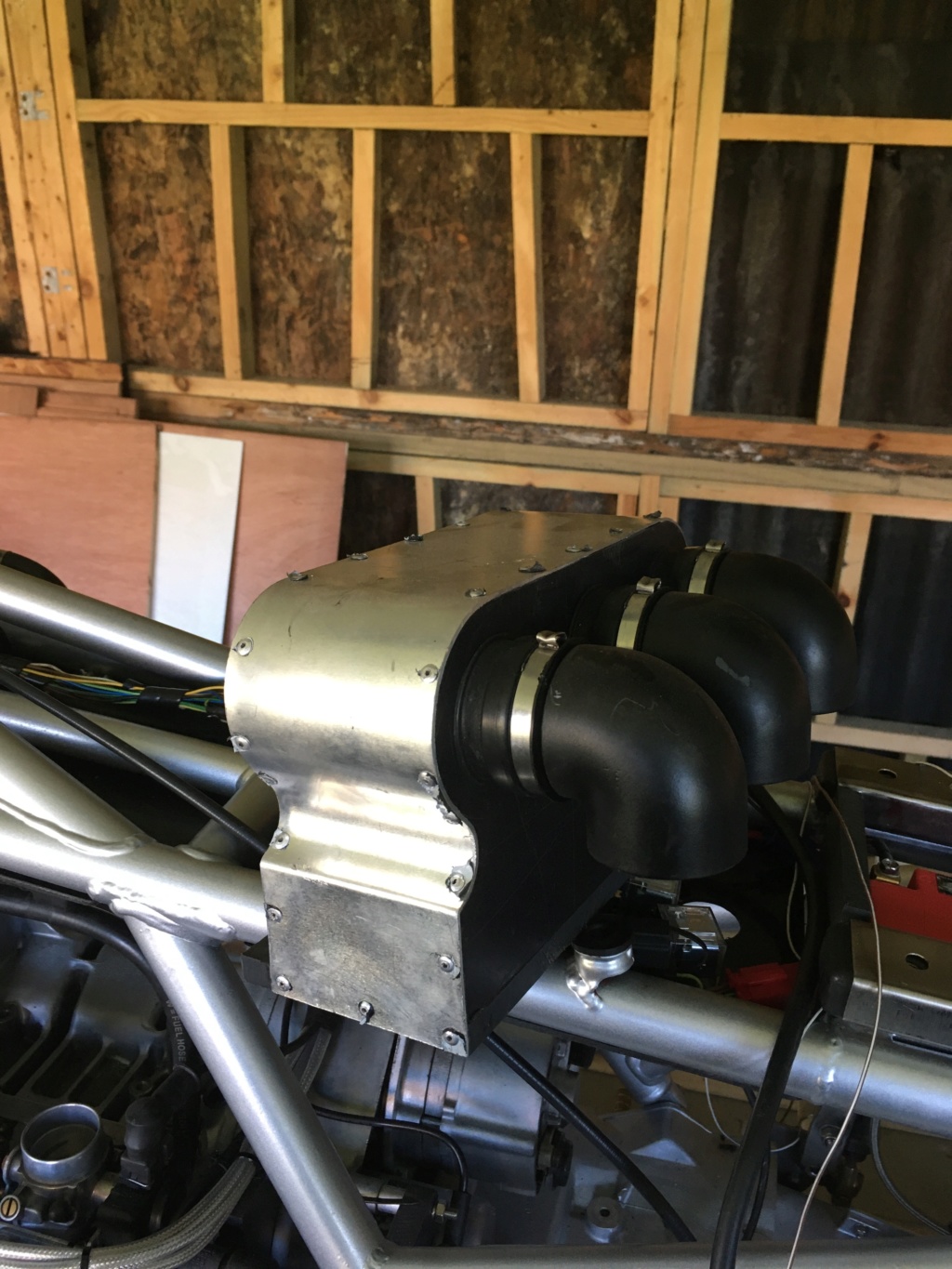
Well here's a couple of pics showing the airbox in situ - to help you make your mind up if it's what you want/worth all the work. This is the K75k remember - the airbox was firstly made for the Madass, because the new frame didn't allow fitment of the OE airbox, so it was a needs must affair. The K75k on the other hand has a 'normal' frame so the daft airbox just isn't necessary at all. I just liked the look of it, no other justification.
Unless, for some reason you need to mount the Jetronic ECU under the frame beneath the tank as I have done in the pictures. This was just a convenient place to put it, after it was evicted from its normal abode to make room for the battery. So, the pictures show how there's room to do this, and still leave plenty of daylight above the engine/beneath the frame.
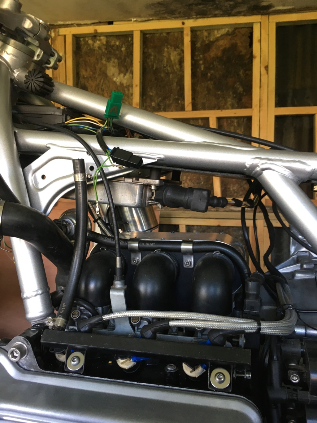
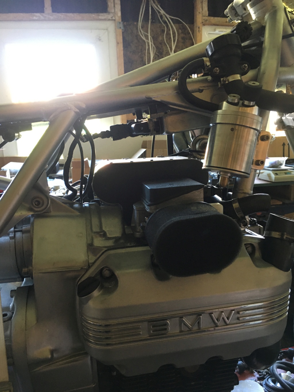
I should make the point that neither the K75k nor the Madass have a cooling fan. So the airbox wasn't designed to clear one. Having said that I do think clearance wouldn't be an issue, but I could check with a spare fan? Note also that the FPR is relocated onto one of the frame downtubes to allow the airbox to sit right up next to the throttle bodies.
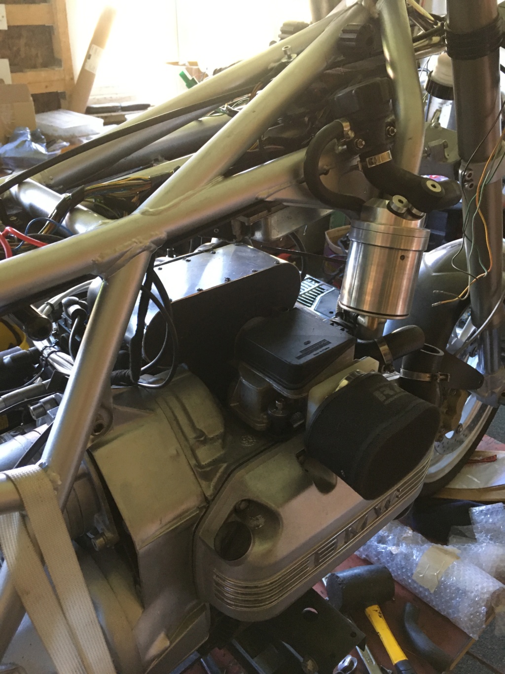
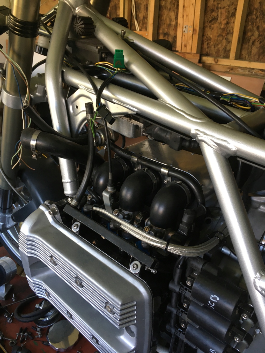
The next pics are just general views of the airbox fitted. The view of the left side shows the fuel return hose to the FPR - the side of the airbox was just a convenient place to clamp it. The 16v throttle cable bracket (and cable quadrant) isn't completely necessary, I just preferred the cable routing that it allows.
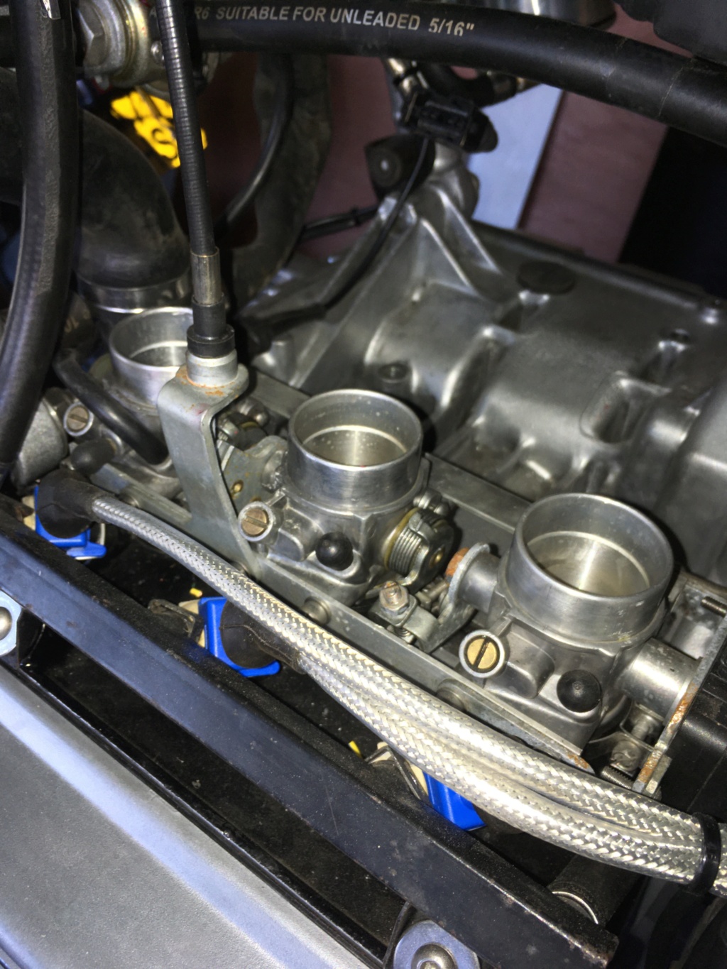
Next up is the airbox removed. Note the tops of the throttle bodies - they have been smoothed to allow the elbows to slide on (quick job with a file and then a scotchbrite wheel)
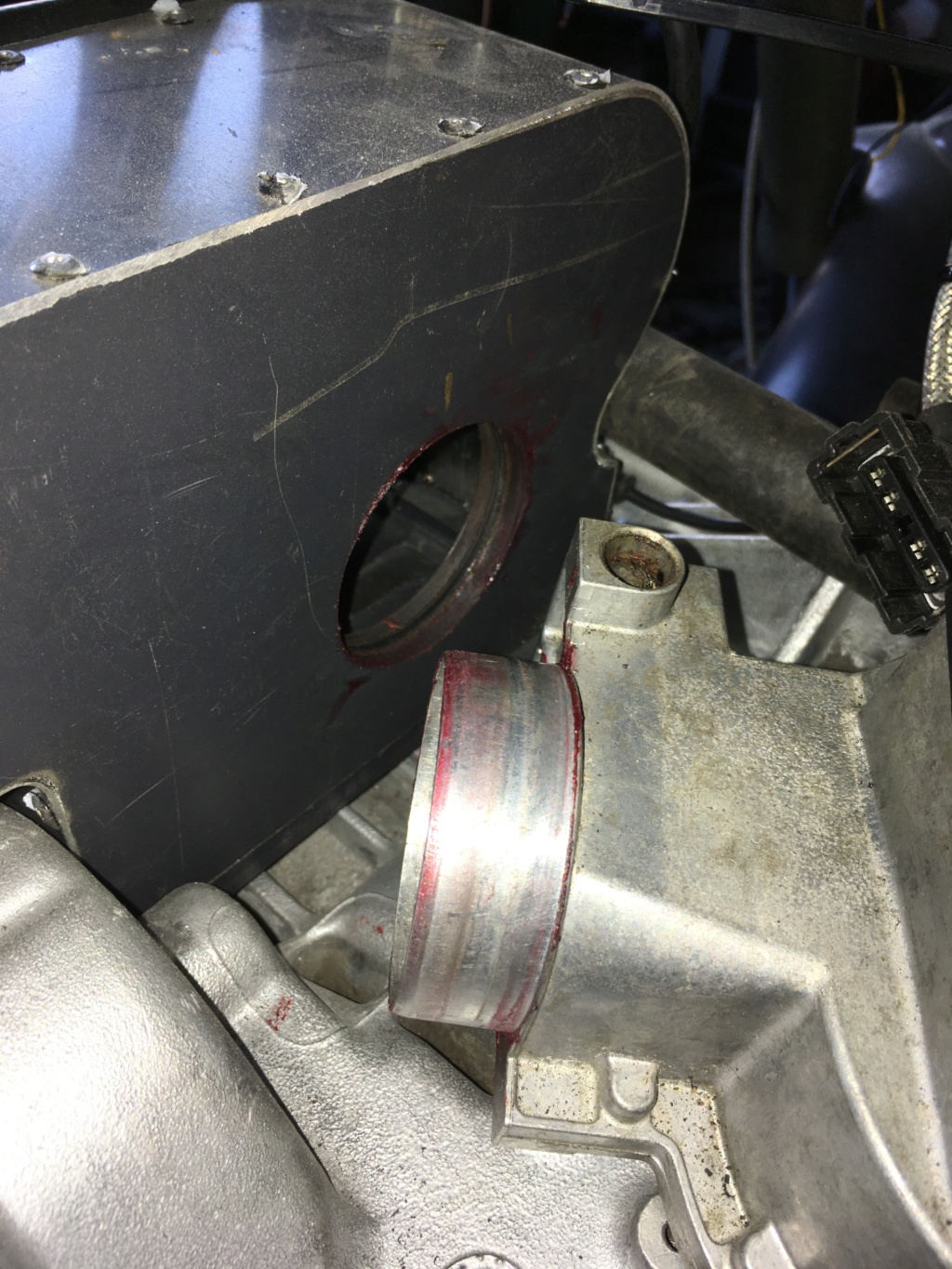
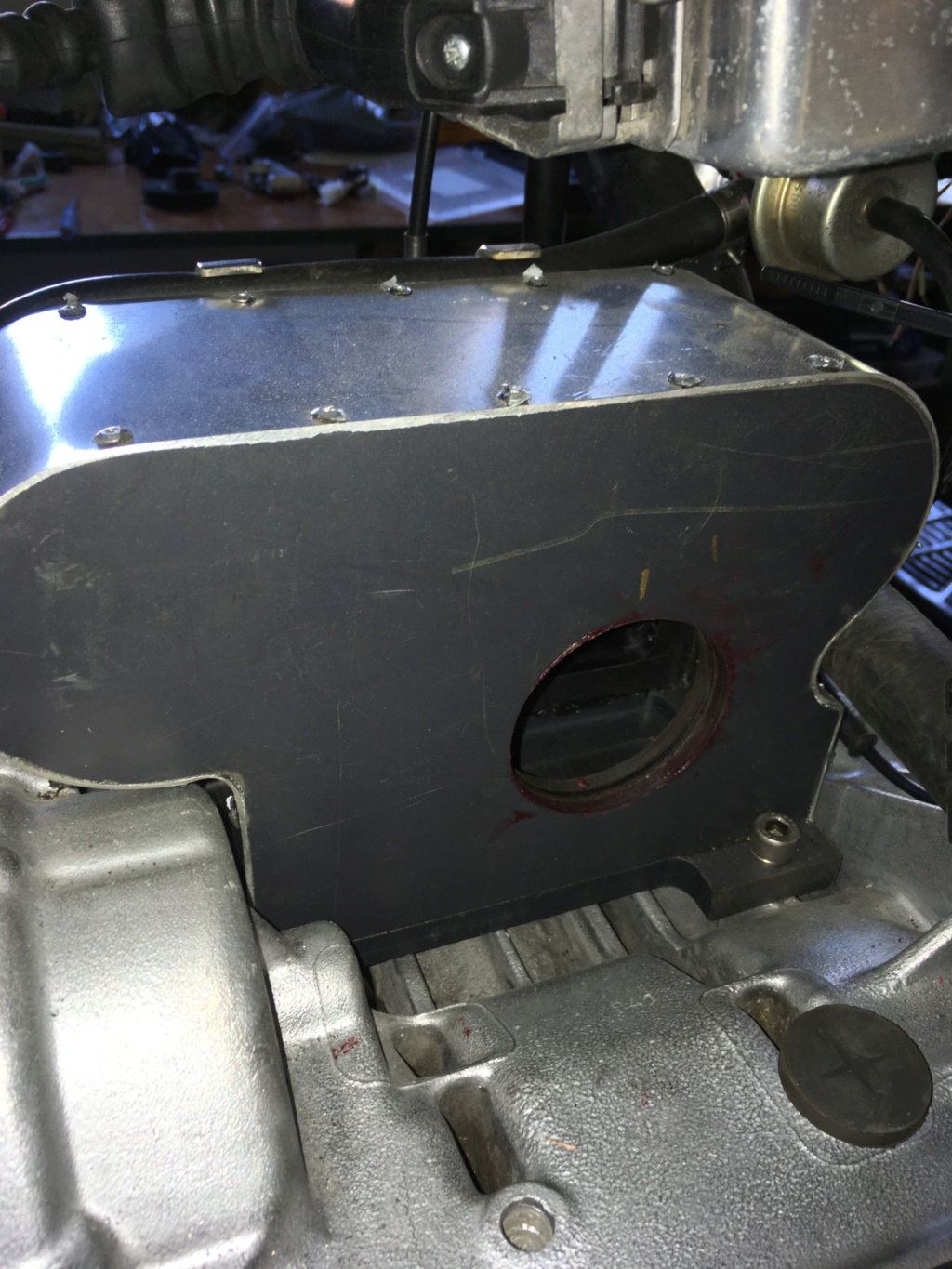
This next pic shows the AFM removed. The AFM outlet stub slides into a bore in the side of the airbox, which is fitted with an O-ring seal (hence the red rubber grease everywhere!). The airbox side just happened to fit into the 4-jaw of my lathe which allowed me to machine the bore and the groove for the O-ring. The AFM is a good secure fit and this method provides its main support and mounting. Note also the radiator hose (the thermostat bypass hose) passing across the front of the airbox - this explains the concave indentation on the front.
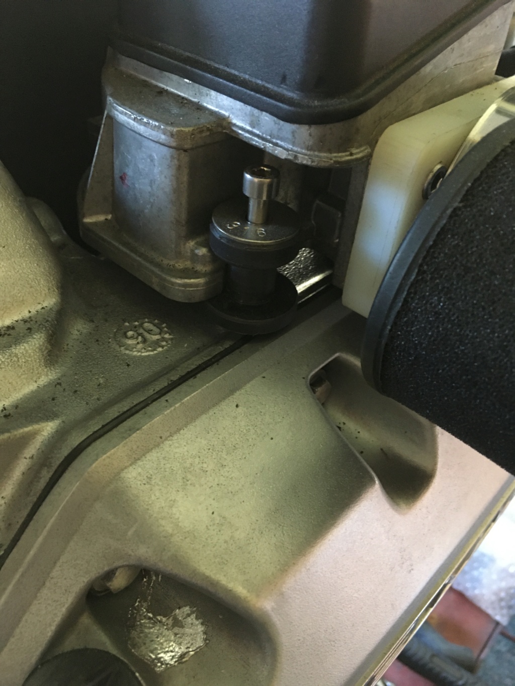
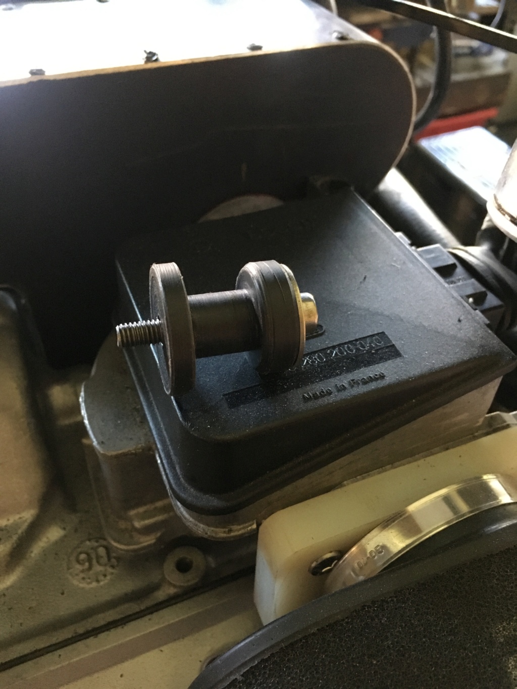
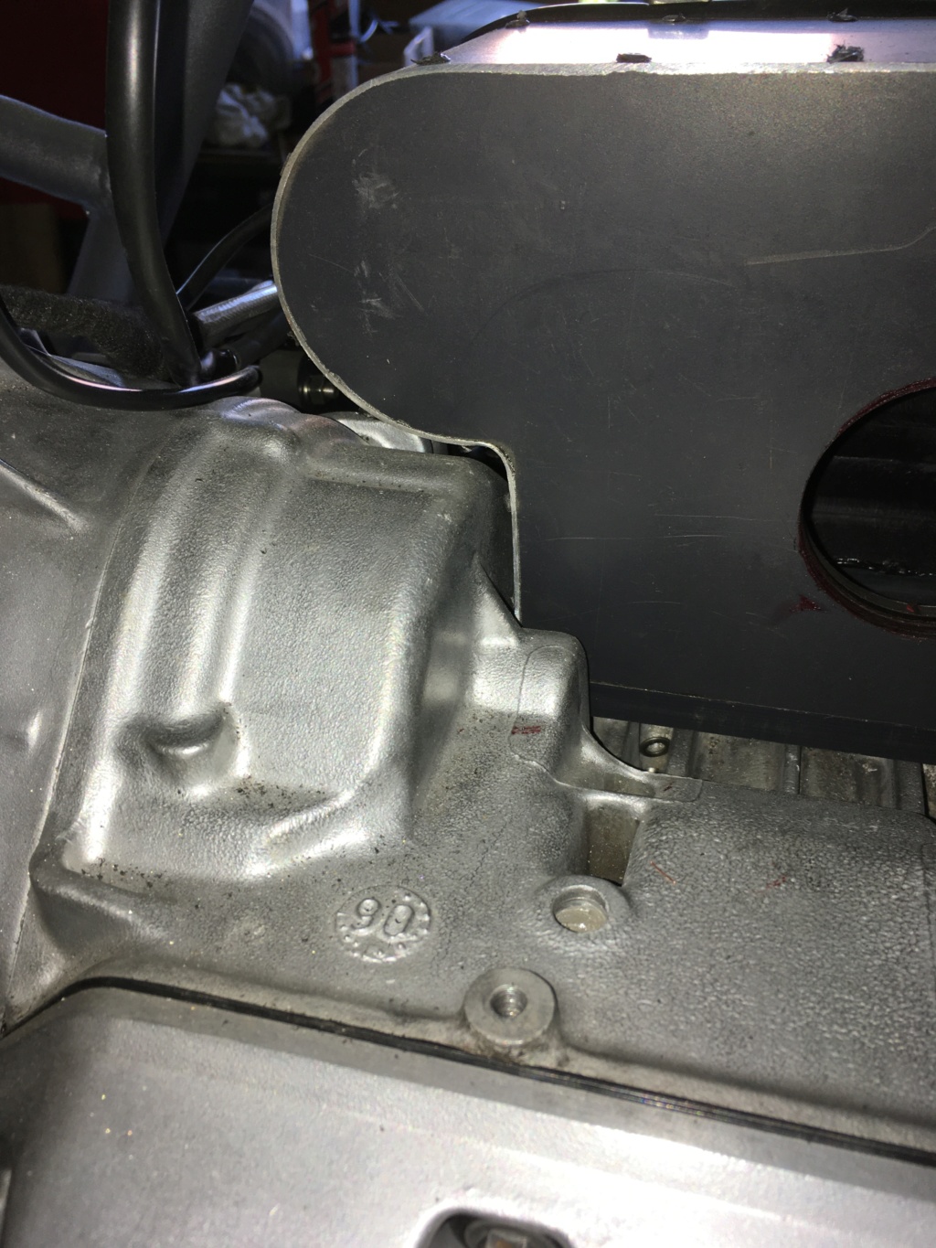
These 3 pics show the other means of mounting the AFM and securing it in place. It's a bit simple and consists of a bobbin screwed into a convenient threaded hole in the top of the engine block, with a corresponding radius filed into the AFM flange as a location. There's also a rubber support (the bottom half of a cut down M8 rubber bobbin/isolation mount) screwed into another convenient hole - 3rd pic. A bit unglamorous, bit is seems to work (but nowhere near as well as the OE setup! oh well) The 3rd pic also shows the sole screwed mounting for the airbox - a tang on the base to pick up another convenient threaded hole in the engine block.
This pic shows the rear of the airbox, which fits closely over the contours of the engine block. The rear-facing 'nose' is necessary to accommodate the inlet runner for cyl no. 3.
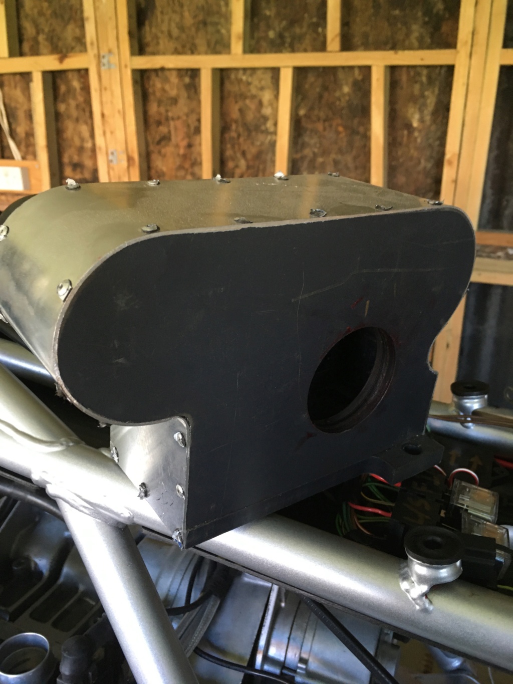
Here's some general pics of the airbox showing its construction. Basically, the sides and base are shaped from 12mm black nylon plate, and screwed together with M4 cap screws. The skin is 1.0mm aloominum sheet, carefully folded and riveted in place. All sealed with tigerseal before assembly.
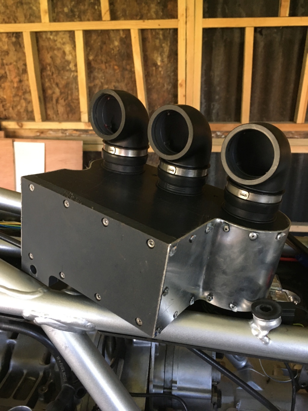
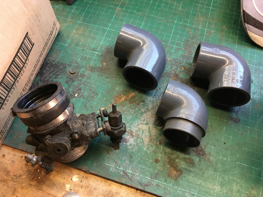
Now for some plumbing. The elbows started life as cheapo PVC solvent weld plumbing fittings. The one in the bottom of the pic has been modified in the lathe: turned down and shortened at one end to match the larger of the two diameters of one of the rubber boots nicked from the top of a standard throttle body (on the left of the pic) and bored out and o-ringed at the other end so's it will slide snugly over the top of a throttle body. A bit tricky to hold in the 4-jaw, but PVC is easy enough to machine once you've got it held square (ish!)
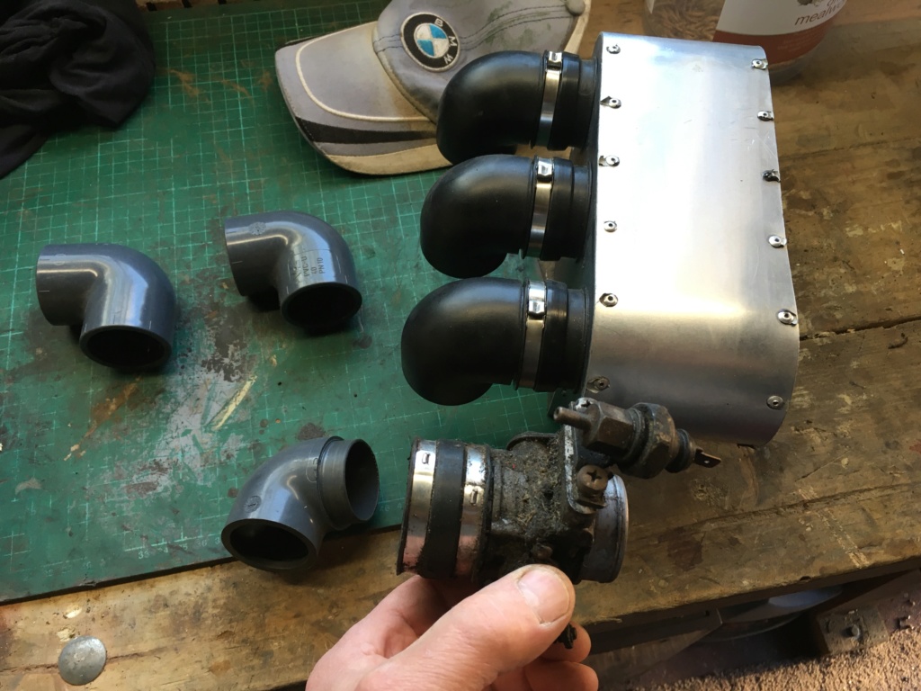
The next pic shows how it all cobbles together: The turned-down end of the elbow fits into the top of the rubber boot (once you've removed it from the grotty throttle body) and the rubber boot then slides over....
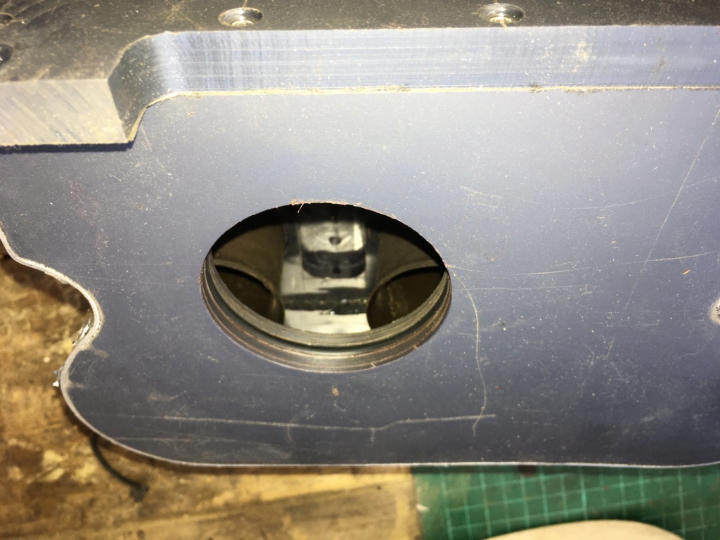
....actually you can't see it. Inside the airbox are three inlet runners nicked from a K1100/16v airbox. They just happen to be the right diameter, and they're straight, unlike the 8-valve ones. I shortened them by about 30mm or so, so's the total runner length was something like the total runner length on an unmolested K75.
3 holes were bored in the airbox side to be a snug fit on the K1100 runners, which were sealed in place (tigerseal again) and fitted with just enough protrusion to suit the stepped inner dimensions of the rubber boots, which were then slipped on to them.
I've just noticed that I've forgotten to install the stainless clips on these.
Here's a not very good pic trying to show the inlet runners inside the airbox


 Re: K75kforkurz Fri Sep 06, 2019 3:55 am


 Wait till he gets the Autosol onto the roof and guttering




 Have no idea if that's going to affect my insurance renewal next year.