BMW K bikes (Bricks)


You are not connected. Please login or register

View previous topic View next topic Go down  Message [Page 1 of 1]


Adil86

Adil86
active member
active member
Good evening everyone

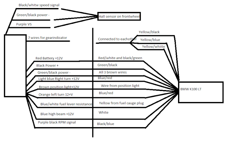
I mounted a digital speedometer on my 87 K100 LT. 
It contains digital speedometer, Tachometer with a pin, fuel indicator, gear indicator and a low battery warning.

The speedo turns on.
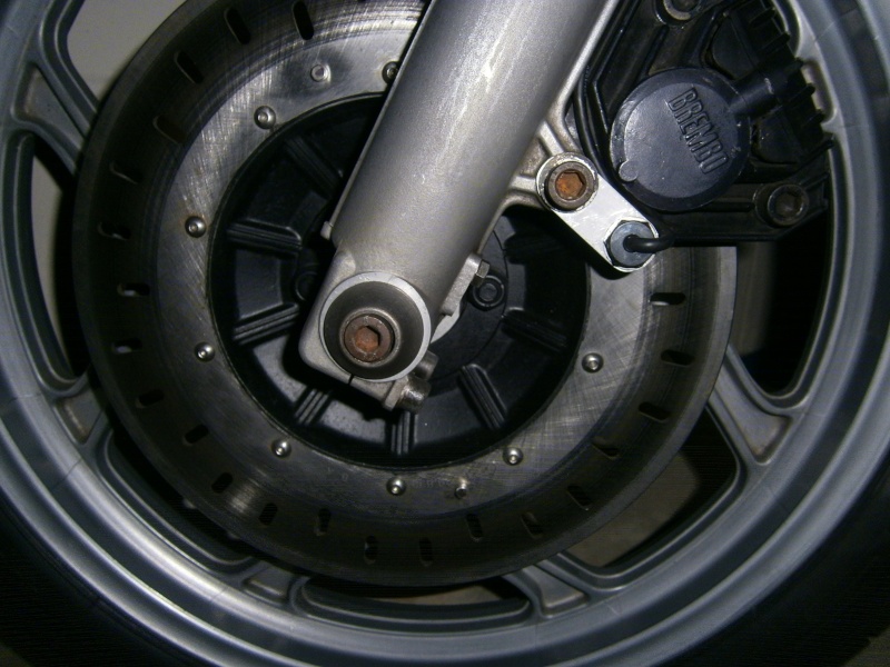
Speedometer works fine via a hall sensor and magnets on the front wheel.
I havent ridden it alot while installing the new speedo but it seems that the fuel indicator works as well. 

Problem 1: 
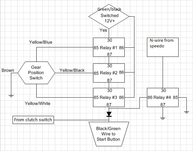
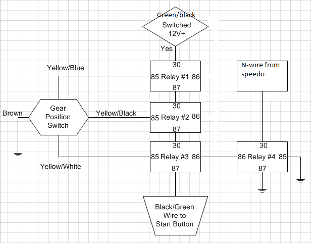
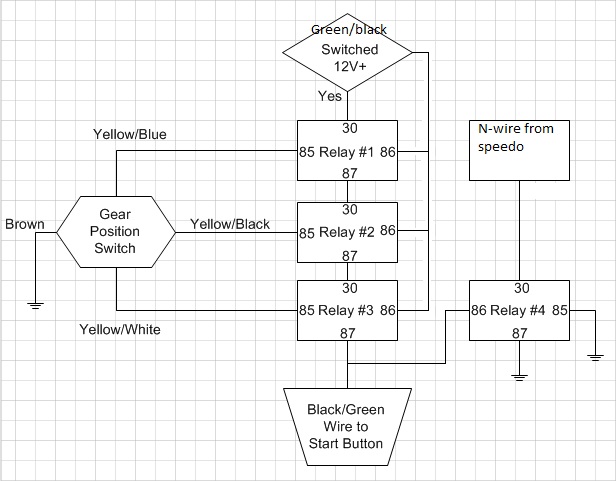
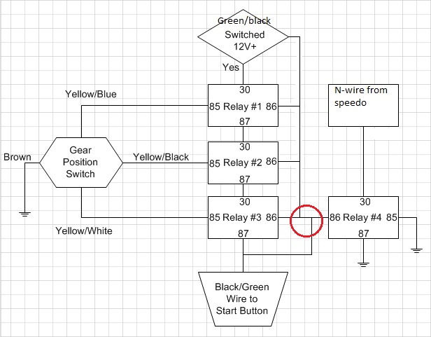
I can turn on the bike without pulling the clutch but the Neutral light does not come on, I read about installing 3 relays on the 3 gear indicator wires. Will this make the Neutral light come on? Where on the bike do i mount these relays? What are these relays called? (what do i search for if i wanna buy them)

Problem 2:
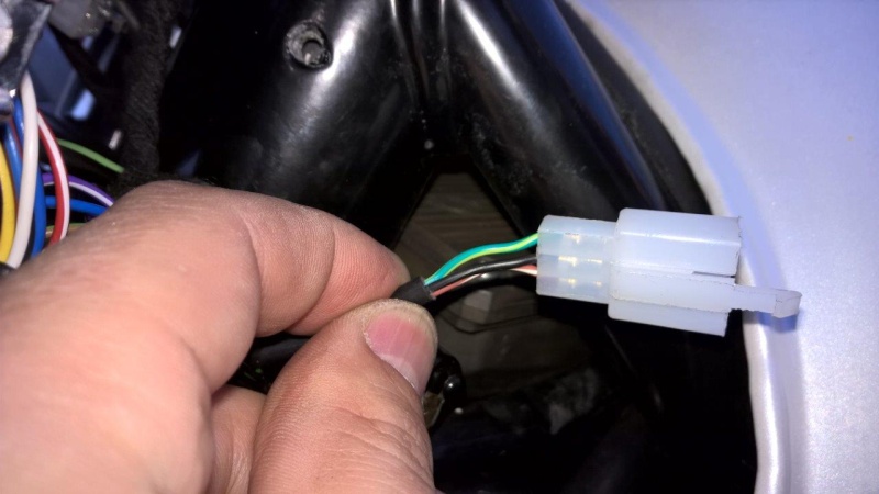
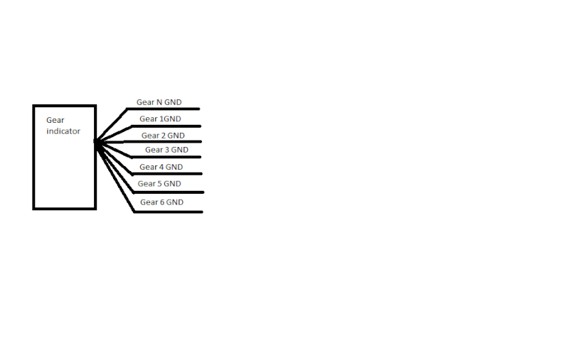
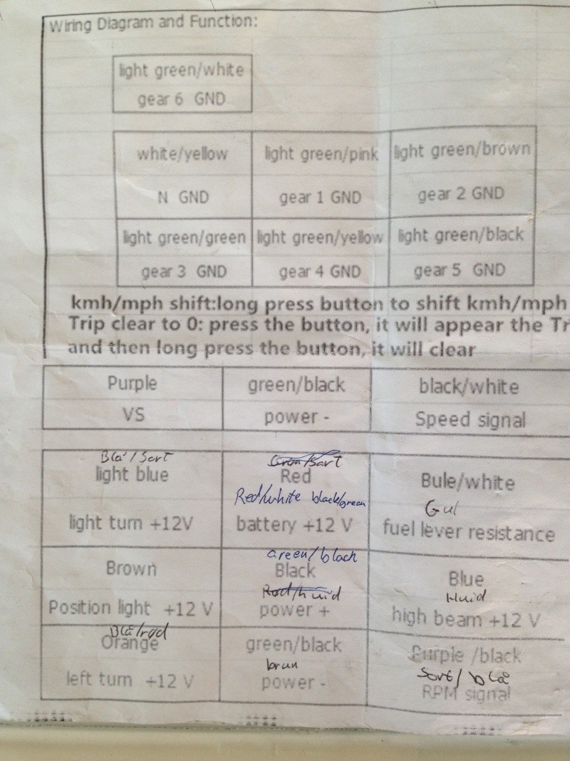
The gear indicator on the new speedo has a wire for each gear 0-1-2-3-4-5-(6) How does the 3 yellow/other colour wires connect with the 6 wires on the speedo? 
The wires from the speedo are called: 
N-GND 
gear-1 GND
gear-2 GND
gear-3 GND
gear-4 GND
gear-5 GND
(gear-6 GND

Problem 3:
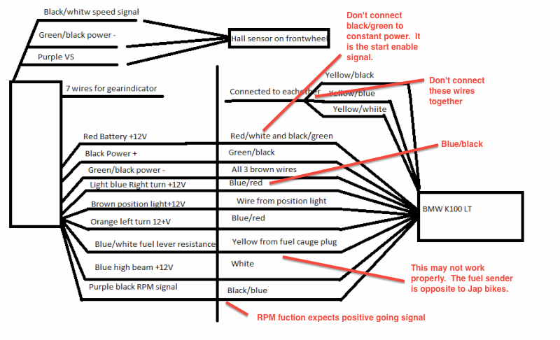
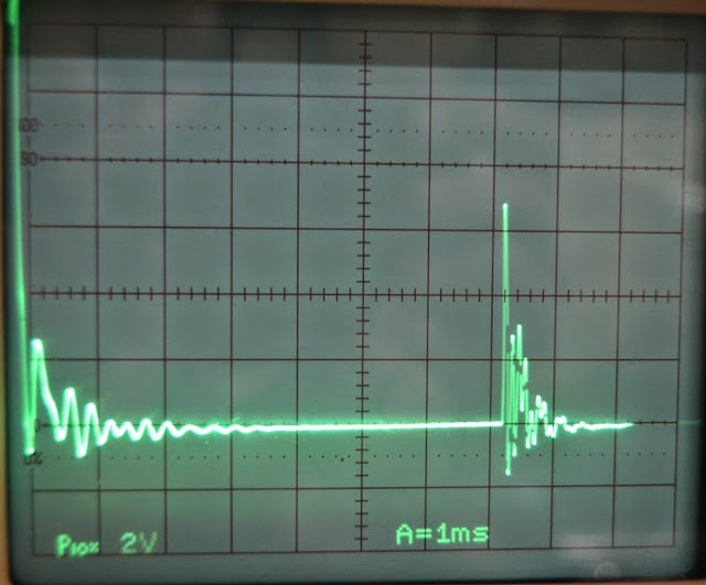
The Tachometer is wired to the black/blue wire on the bike but it does not work. It stays on 2000rpm and jumps about 500rpm up and down every once and a while.

Problem 4:
The battery warning indicator on the speedo keeps blinking. Do i have to connect the blue loading control wire somewhere on the new speedo?

I hope you guys can help me with these problems :-)
Let me know if you need more informations.

Adil


robmack

robmack
Life time member
Life time member
What is the manufacturer of the speedo you selected?  This information is missing from your post.

I have modified my K75 to use an aftermarket speedo.  Please read the blog I created to understand how I accomplished this.  Pay attention to the pages on Motogadgets Speedo and K75 rewiring because they contain information that can potentially solve your problems.

The relays used to emulate the neutral detect circuit can be almost any type.  This is because the current drawn by the circuit is extremely small.  If you are good at electronics, you can choose microminiature SPDT relays and fit them on a small circuit board.

It is not possible to connect the three wires to the six wires on your speedometer.  Some motorcycles output different voltages depending on the gear selected.  Is it possible that your speedo is looking for this type of input?

Can you provide a schematic drawing as to how you have wired up your speedo?

If the battery indicator is blinking, possibly you have to program the speedo to tell it the value that represents a low battery voltage.  The speedo should be able to sense the battery voltage from the wire that is supplying the speedometer with its power source; you should not need any additional wires.


Last edited by robmack on Thu Jun 12, 2014 12:31 am; edited 1 time in total


__________________________________________________
Robert
1987 K75 @k75retro.blogspot.ca
http://k75retro.blogspot.ca/
    

Adil86

Adil86
active member
active member
I went for a chinese no name speedo. Proberbly different opinions on that choise :-)
Here's a link

http://www.ebay.co.uk/itm/12000rpm-KMH-MPH-LCD-Digital-Odometer-Speedometer-Tachometer-Motorcycle-Scooter-/201077149525?pt=UK_Motorcycle_Parts&hash=item2ed121cf55

ill try with the relays, sounds simple enough.

Yes its proberbly made for motorcycles with a wire for each gear. It would be nice with a gear indicator tho.

Its the first schematic i have ever made. Hope its understandible :-)


[img(26px,26px)]Electrical trouble mounting aftermarket digital speedo Schema16[/img]


Thanks


Adil


robmack

robmack
Life time member
Life time member
Electrical trouble mounting aftermarket digital speedo Schema10

Can't imagine why the RPM counter is not working.  Black/blue is a negative going 12 volt signal right from the coil.  The specs say they want a positive signal. Maybe they want positive going.

Your neutral detect circuit should output to black/green.  Don't connect it to constant 12 volts from the red/white wire.  That's dangerous IMO.

I don't know what a position light is (Brown wire)

The TGPI outputs a BCD representation of the gear number on the three wires.  Your circuit that connects those wires together is probably not going to do what you want it to do.  Make the neutral detect circuit instead.  Connect the black/green wire to the output of that circuit.  Also, you don't show any connection for a neutral indicator into your speedometer.  Should neutra out from the relay circuit be routed to one of the 7 gear indicator wires?


__________________________________________________
Robert
1987 K75 @k75retro.blogspot.ca
http://k75retro.blogspot.ca/
    

Adil86

Adil86
active member
active member
Thank you for the corrective schematic. Makes it so much easier when its on a schematic.

Maybe. Where and is there positive signal from the coils?

I will start working on the neutral detect circuit soon

Is this how to do it?
[img]Electrical trouble mounting aftermarket digital speedo Neutra11[/img]

Yes one of the 7 wires from the gear indicator is for the Neutral so that should be easy.
[img]Electrical trouble mounting aftermarket digital speedo Gear_i10[/img] 


A position light is like a parking light. A small bulb in the light housing under the main beam.


Adil


robmack

robmack
Life time member
Life time member
Here is a photo of an oscilloscope trace showing the tach signal output on the black/blue wire of my K75.
Electrical trouble mounting aftermarket digital speedo Coil%2520output%2520at%2520idle

The vertical is 2V/division and the horizontal is 1mS per division.  This shows a Peak-peak of ~12V and ~2mS pulse width.  The bike was on fast idle of about 1000 RPM.  The interval between pulses was 7mS.

Check with the manufacturer to see if this output is compatible with your aftermarket speedo.


__________________________________________________
Robert
1987 K75 @k75retro.blogspot.ca
http://k75retro.blogspot.ca/
    

Inge K.

Inge K.
VIP
VIP
This would function better:

Electrical trouble mounting aftermarket digital speedo Sjema10


__________________________________________________
Inge K.
K100RS -86. (first owner), K1100LTSE -94.
    

Speedaddictedberk

Speedaddictedberk
Silver member
Silver member
The battery indicator on my koso speedo stays on for a while after starting until the voltage has recovered. Yours may be similar.
For the rev counter I used a site wrapped around one of the plug leads as it wouldn't work with the normal output. Speedo wanted positive.

http://leportphotographic.co.uk
    

Adil86

Adil86
active member
active member
@robmac
@Inge K.
Ok so i installed the neutral detect circuit as instructed. The bike starts without pulling the clutch and the Neutral light is on. But the Neutral light stays on at all time. What did i miss? 

@Speedaddictedberk
I will have to see about the batteri indicator when i get  the bike back on the street. How do you make this site wrapped?

Adil


Inge K.

Inge K.
VIP
VIP
Adil86 wrote: But the Neutral light stays on at all time. What did i miss? 

Have you wired the relays as in reply #7.
Or have you connected relay 3 & 4 together as in post #5.


If the later the neutral light will stay on as long the ignition is on.


Electrical trouble mounting aftermarket digital speedo Sjema11


__________________________________________________
Inge K.
K100RS -86. (first owner), K1100LTSE -94.
    

robmack

robmack
Life time member
Life time member
Can you post a link to the manufacturer's documentation?

The circuit Inge posted should work in the following way.
Bike in Gear
If any gear is selected on the transmission, the TGPI switch will have one or more wires open circuit.  In this state, one or more relays 1, 2 or 3 will not be engaged.  Therefore the output on relay #3 to the Black/Green wire will be off and the start circuit will not work.  At the same time, Relay #4 receive no power on its coil and it is disengaged as well.  The Neutral light is open circuit in this state; no current can flow through Relay #4 contact to ground.  The Neutral light should be off.


Bike in Neutral
When the bike is in neutral, all three wires from the TGPI switch are grounded; relays 1, 2 and 3 are all engaged and +12V is delivered to Black/Green wire and Relay 4's coil.  The bike can start without the clutch pulled in because +12V is now applied to the start circuit.  Relay 4 is engaged because power is applied to its coil.  Current can now flow through Relay $ contacts to ground and the Neutral light will turn on.

This circuit ASSUMES the neutral light in the speedo is an LED and had one side connected internally to +12V.  If this is not the case with your speedometer, you will have to tell us what the manufacturer expects for the installation.


__________________________________________________
Robert
1987 K75 @k75retro.blogspot.ca
http://k75retro.blogspot.ca/
    

Adil86

Adil86
active member
active member
Thank you for the Quick responce 


@Inge K. It is wired exactly as in reply #7


@Robmack 

Thank you :-) i understand the way it works now. But i still dont know why it dosent work. I have done exactly as shown on the diagram.
Does the Brown wire for the TGPI switch need to be grounded somewhere else? I Think all Brown wires should be grounded by now.


Here is what came with the speedoElectrical trouble mounting aftermarket digital speedo Cid:(null):
Electrical trouble mounting aftermarket digital speedo <a href=Electrical trouble mounting aftermarket digital speedo Foto_210" />


Electrical trouble mounting aftermarket digital speedo <a href=Electrical trouble mounting aftermarket digital speedo Foto_310" />


And here are the relays i used:
Electrical trouble mounting aftermarket digital speedo <a href=Electrical trouble mounting aftermarket digital speedo Foto_110" />


Electrical trouble mounting aftermarket digital speedo <a href=Electrical trouble mounting aftermarket digital speedo Foto10" />

pin 1- 86
pin 2- 85
pin 3- 30
pin 5- 87
There must be a logical explanation.....

PS: Dont mind the notes on the pictures :-)

Adil


Inge K.

Inge K.
VIP
VIP
Was a bit curious about the documentation regarding the gear/neutral indicator,
but the function was as I assumed........so the relay setup should have functioned Electrical trouble mounting aftermarket digital speedo Idunno10.


I would guess that it would be a good idea to check the relay wiring one more time.


Last edited by Inge K. on Sun Jun 15, 2014 4:41 pm; edited 1 time in total


__________________________________________________
Inge K.
K100RS -86. (first owner), K1100LTSE -94.
    

Adil86

Adil86
active member
active member
Exactly @Inge K. 

Update: 
I took it all apart and put it back together again. Now The neutral light is only on when i pull the clutch...... confusing....
I guess working in the sun all day is not the best :-)

Adil


Inge K.

Inge K.
VIP
VIP
To avoid this you need a diode in the circuit between the relay connections and clutch switch connection...........I'll correct the drawing.


Electrical trouble mounting aftermarket digital speedo Sjema12


__________________________________________________
Inge K.
K100RS -86. (first owner), K1100LTSE -94.
    

16Back to top Go down   Electrical trouble mounting aftermarket digital speedo Empty Contact Fri Mar 20, 2015 4:07 pm

PiotrK100

PiotrK100
Silver member
Silver member
Hi Adil86
Will you please contact me? I PM you but you did not respond. I have same speedo and will try to connect now, and need help.

http://www.xenum.pl
    

Duncan-K

Duncan-K
active member
active member
I just had to chime in with my $0.02 worth here...  As you know, these speedos don’t play very nicely with the K.  They are cheap, the quality appears to be OK, but documentation and support is non-existent.  At idle, the tacho sits on about 4,000 – a little optimistic...  After lots of experimenting, here’s what I came up with:

Get a 100K ohm 0.5 W resistor and a 10 nF 630V capacitor.  If you are in Aus, Jaycar have them – costs are 46c (for 8 resistors) and 45c for the capacitor.  Part numbers are RR0620 and RG5201 respectively.

The blue/black from the coil is the rev counter signal.  Instead of connecting this directly to the chinese tacho’s purple/black wire, connect the capacitor in series.  In other words, the cap sits between the blue/black and the purple/black connection.  Then, from the tacho side of the capacitor joint, join one end of the resistor to the capacitor – purple/black joint.  The other end of the resistor is joined to a brown earth.  (I haven’t uploaded a diagram, so imagine a T-connection.  The wire from the tacho goes through the resistor to earth.  The same connection, tacho side on the resistor, goes through the cap to the coil wire.)  Shrink-wrap the capacitor/resistor/joint and tuck it in the headlight housing.

Then, hold the button on the back of the speedo and power on.  After a few secs it will go into Setup mode.  Make sure the tacho setting (the last digit) is on 2.  BTW, I found that 897 for the speedo wheel size is spot on.  I have two magnets on the front disk – spaced 180 degrees apart.

The fuel gauge is fairly accurate on the 5 setting.  I extended the BM’s yellow wire from the accessory plug, and it’s connected to the speedo’s blue/white wire.

I haven’t worried about the 3-relay neutral switch trick.  Neutral is so easy to find – I don’t need to see a ‘N’ on the speedo.  I haven’t figured out how to convert the 3 wires from the GPI to the speedo’s 5 wires for the gear position indicator yet!

Re the clutch-in start issue – I got around this by connecting the loom’s green/black and black/green wires together, and this was joined to the tacho’s black wire.  If you look at the K wiring diagram, the clutch switch function is just to prevent over-start.  With my bodgy, the starter will turn if you hit the button when the engine’s running – but who’s going to do that...?  Or, am I missing something about the clutch-in/neutral issue?


PiotrK100

PiotrK100
Silver member
Silver member
Duncan-K thanks for information. Will do the trick with capacitor and resistor, so hopefuly will be able to see the rpm of my engine.
In fact neutral and gear number is not that important and I can live without, but cant leave without fuel level indicator which does not work. I connect yellow to blue/white and nothing happens. BTW changed settings on 5 in speedo. Maybe I did screw up something reversing gauge that is inside the tank? But how come? Should be working.
Anyway many thanks for your help and will try to connect all again as long as the patience lasts. If you have any suggestions regarding the fuel indicator....
Could you send me a pic how you attached magnets and sensor? I already did with mine sensor but with magnets have some issues.

http://www.xenum.pl
    

charlie99

charlie99
VIP
VIP
Duncan-K wrote:I just had to chime in with my $0.02 worth here...  As you know, these speedos don’t play very nicely with the K.  They are cheap, the quality appears to be OK, but documentation and support is non-existent.  At idle, the tacho sits on about 4,000 – a little optimistic...  After lots of experimenting, here’s what I came up with:

Get a 100K ohm 0.5 W resistor and a 10 nF 630V capacitor.  If you are in Aus, Jaycar have them – costs are 46c (for 8 resistors) and 45c for the capacitor.  Part numbers are RR0620 and RG5201 respectively.

The blue/black from the coil is the rev counter signal.  Instead of connecting this directly to the chinese tacho’s purple/black wire, connect the capacitor in series.  In other words, the cap sits between the blue/black and the purple/black connection.  Then, from the tacho side of the capacitor joint, join one end of the resistor to the capacitor – purple/black joint.  The other end of the resistor is joined to a brown earth.  (I haven’t uploaded a diagram, so imagine a T-connection.  The wire from the tacho goes through the resistor to earth.  The same connection, tacho side on the resistor, goes through the cap to the coil wire.)  Shrink-wrap the capacitor/resistor/joint and tuck it in the headlight housing.

Then, hold the button on the back of the speedo and power on.  After a few secs it will go into Setup mode.  Make sure the tacho setting (the last digit) is on 2.  BTW, I found that 897 for the speedo wheel size is spot on.  I have two magnets on the front disk – spaced 180 degrees apart.


good solve Duncan

some have almost given up trying to find a workable solution for similar things

cheers


__________________________________________________
cheezy grin whilst riding, kinda bloke ....oh the joy !!!! ...... ( brick aviator )

'86 K100 RT..#0090401 ..."Gerty" ( Gertrude Von Clickandshift ) --------O%O
'86 k100 rs.. #######..  "Fred " (f(rame) red ) ( Fredrick leichtundschnell ) - -
bits and pieces from many kind friends across the k100 world ...with many thanks ..
1987 k100rs ########   "Red"  - (red sports rs TWB style )
1989 K100rt #009637   "Black Betty"  (naked rt ala Nigel , now sporting an rs main fairing )
    

Duncan-K

Duncan-K
active member
active member
PiotrK100 - are you connecting the correct yellow for the fuel gauge?  The one on the instrument harness won't work - it's just for the low-level light.  As I understand, a fuel gauge is an optional item, that's why the connector is in the relay box.  I found the unused plug in the relay box, and then to confirm I had the correct yellow, I disconnected the fuel tank connector, and put one lead of a meter on each.  Then, from the plug in the relay box, I ran a single wire to the headlight pod for the speedo's fuel gauge.  Maybe not all models have the unused fuel gauge connector in the relay box?

I didn't use the magnets that came with the speedo.  They are too bulky!  I bought a pack of 10 rare earth disc magnets on ebay for a few $.  They are small - 7mm in diameter, and twice as powerful as the supplied magnets.  I super-glued them onto the disk, and then made a small aluminium bracket to hold the sensor.  The smaller magnets will fit between the disk and the fork stanchion - the supplied magnets won't.  (In the pic, magnets are at 11 and 5 oçlock...)

Electrical trouble mounting aftermarket digital speedo P5080210


PiotrK100

PiotrK100
Silver member
Silver member
Electrical trouble mounting aftermarket digital speedo Avatar10
Duncan-K thanks again.
Well, can not locate that yellow wire you are talking about:
http://hrsbstaff.ednet.ns.ca/bvogel/K100/download/electrical/diagrams/early%20K100%20diagrams/interactive_diagrams.htm
will you please help me in that matter? Just have no idea which wire it should be to connect to the speedo instead.
With magnets will follow your attachment, so will buy neodym magnets and glue them to the disc, smaller but stronger.

One case more regarding that speedo, together with (that non working) fuel indicator is blinking battery sign, which I do assume should show the low voltage, or?

http://www.xenum.pl
    

Duncan-K

Duncan-K
active member
active member
I don't believe all models have the optional fuel level sender/wiring.  Mine is an '85 - I think the earlier models had a sender for the warning light only.
Yes, my low battery indicator used to flash sometimes.  Since adding the resistor/capacitor, it has stopped flashing, so maybe the "tacho tamer" fix also solved this problem?
I'm quite happy with the speedo now.  Other than no N light and the gear pos indicator, it works really well.


charlie99

charlie99
VIP
VIP
quite likely Duncan

I would imagine the 12 volts pulsing constantly may affect the stability of the instruments 

now capacitivly coupled and  attenuated would now have less disruption to the rest of the electronics which share the same earth reference inside


__________________________________________________
cheezy grin whilst riding, kinda bloke ....oh the joy !!!! ...... ( brick aviator )

'86 K100 RT..#0090401 ..."Gerty" ( Gertrude Von Clickandshift ) --------O%O
'86 k100 rs.. #######..  "Fred " (f(rame) red ) ( Fredrick leichtundschnell ) - -
bits and pieces from many kind friends across the k100 world ...with many thanks ..
1987 k100rs ########   "Red"  - (red sports rs TWB style )
1989 K100rt #009637   "Black Betty"  (naked rt ala Nigel , now sporting an rs main fairing )
    

PiotrK100

PiotrK100
Silver member
Silver member
Mine is also 85 but during some changes in wires I assumed that harnes is from early models. It is starnage but 100% according to the wires colours. But looking at all diagrams I can not find that cable you talk about for fuel indicator, so maybe I should  looking for that cable without taking care about diagrams?
Will do the magic change with resistor/capacitor soon so will see if that works. Well, I can live without gear indicator and neutral but fuel gauge would be helpful.

http://www.xenum.pl
    

PiotrK100

PiotrK100
Silver member
Silver member
Duncan -K.
With a help I find out the misterious yellow wire you plug from the tank gauge. Mine brick is an old version and does not have additional wire to connect external fuel gauge. End of story Sad 
But need your help with speedo, hope the last one. I can not calibrate the proper km/h no matter I change the values it shows about 1/5 of the speed. In my opinion changing that "flat tire" value changes nothing in speed. Can you explain me what is that three figures on speedo for?
But, also I may did a mistake because I needed to remove connector cover and I may reconnect them in a wrong position. Please look at the picture and tell me if your colours are connected as mine?
Of course I did superglue two magnets as you did.

Electrical trouble mounting aftermarket digital speedo Wtyczk11

http://www.xenum.pl
    

26Back to top Go down   Electrical trouble mounting aftermarket digital speedo Empty Neutral light Wed May 13, 2015 8:41 pm

Motorbike Mike

Motorbike Mike
Life time member
Life time member
I've been playing with the wiring on my K100 8v. I'm using a 16v harness because I'm using Motronic efi.
I got bored of the neutral light issue and modified a switch from an R1100.  This only has 2 wires and cuts out the need for extra components.

It worked for me!


Sponsored content


View previous topic View next topic Back to top  Message [Page 1 of 1]

Permissions in this forum:
You cannot reply to topics in this forum