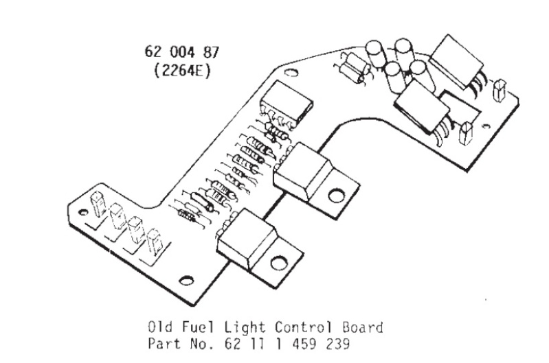
This may seem like some useless pursuit, but I'm wondering if anyone has the ability, training & experience to help me with a fuel light board circuit.
Again, You can just throw an old shoe at me if I'm being ridiculous here but I'm trying to "Reverse Engineer" a fuel light system.
I have a 1985 K100rs. I used to have a newer 85K100rs as well, Although few people have any love for the original "Duel" fuel lights, mine on the 1st bike worked pretty well & I liked them.
That said, I no longer have the original instrument cluster from my current 85 K100rs. I currently have a speedo unit on it removed from a 1987 K75S. It has a 9 screw housing, Gortex vents and a single 4L fuel lamp. I also have a used 1985 k100rt speedometer assy that I'm using for various parts It had 235,000 miles on it
The object of my "ridiculous adventure" is that I'm attempting to reverse engineer the newer speedo assy to operate with both early fuel lights.
I have completed my work so far but I have yet to test it because I have another unit on the bike for an extensive test that I intend to sell. If everything operates properly on that unit.
So.....On to the story: I have the early 2 light board designed for a 7 screw housing in the newer 9 screw unit. I have both lights installed in the foil ribbon. I have fabricated and added a second "connection Pin" in the foil ribbon for the second lamp & connected it to the early board (T1).

I have changed the lenses in the front to reflect the 7L & 4L lamps. I still have some doubts about the way a couple of components are screwed down to the back side of the Tach. The old style Tach. had metal plates across the back & then the fuel board componats (I don't know what they are called) are to be screwed down on top of the metal plate. The plates do not appear to be electrically connected to anything, but the newer tach. does not have them. So the components are screwed down directly to the plastic housing.

>>>
I just realized looking at the photo above that I still need to fabricate and install another pin in the foil ribbon at the other end of the fuel board, 2 pins to the left of the pot.Anyway.....continuing, just before I closed up the housing for a test, I spied 2 more defects that I have attempted to correct but I have some considerable doubts about:
#1 All 3 legs of the Pot. (Shown above) were found to be completely broken loose from their solder connections.
#2 The Diode in the following photo had never been installed in the hole in the board on one end & of coarse never connected & soldered. See below>>>

I have re-soldered the 3 legs of the Pot. re-installed the leg of the diode & soldered it to the board as well.
I regret that I did not get some pics of the back side of the board and the solder joints.So here are some questions: I'm not good at following those tiny printed circuit ribbons across a board under the green shellac. I'm thinking that it's entirely possible that I have some of the legs on the Pot shorted over to the adjacent circuit or across 2 circuits. The same concern exists with the one end of the diode.
I have seen the electrical schematic of the fuel lights circuit, but I'm not technical enough to interpret it.
I'm hopeful that someone has a closeup photo of the bottom of the early 2 lamp board & can help me compare it to the schematic. (A formidable task).
Finally I'm wondering what you think my chances of succeeding are, once I get the other foil ribbon pin soldered in?
PLEASE do not tell me "it's easier if you just go out and get another used 85 speedometer and fix it up"
Regards, ibj...
Inge K. wrote:A closer look at the year of Themasons bikes, they probably got a thermistor sensor.
On both the early (two lamp), and the later (single lamp) version the current to the
thermistor(s) self heating circuits could be adjusted (nomally set to 95 mA).
Later version:


 dual fuel indicator Wed Dec 05, 2012 1:44 am


 ....And i would have too if you hadn't told me!


