1

 Checking the timing of a K100 Mon May 28, 2012 5:38 pm
ReneZ
Life time member

As referred to elsewhere I did some preventive maintenance and decided to renew my timing chain and look at the plastic guides and the timing chain tensioner as I had some rattling from the front at times. The bike has done about 85-90K miles and I was unaware if it had ever done before. I also took the opportunity to modify the tensioner somewhat, as BMW had modified the original one some time and fitted a piston like dish end on the spring. I ended up fitting a ballbearing ball that sat well on the spring, but didn't close off the plunjer.
I decided to take of both side covers to have a quick look at my rivets (6 rivet output shaft ) as well.

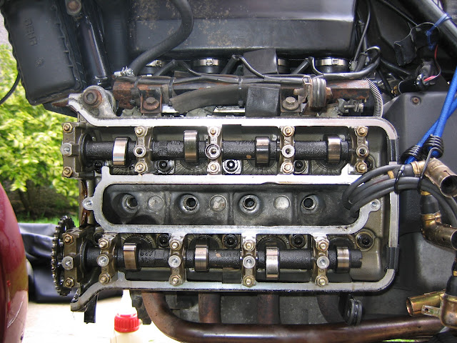
I sprayed the cams with some dry teflon lube to ensure easy movement over the valve plates (I checked/adjusted clearance as well), tied the spark plug leads out of the way and took the spark plugs out (to be renewed) to prevent pressure build up whilst turning the engine over.
After I had removed the chain I compared old with new. One can measure length or measure difference between 'pulled' and 'pushed' links, but bending the overal chain slightly showed a good reason to renew.
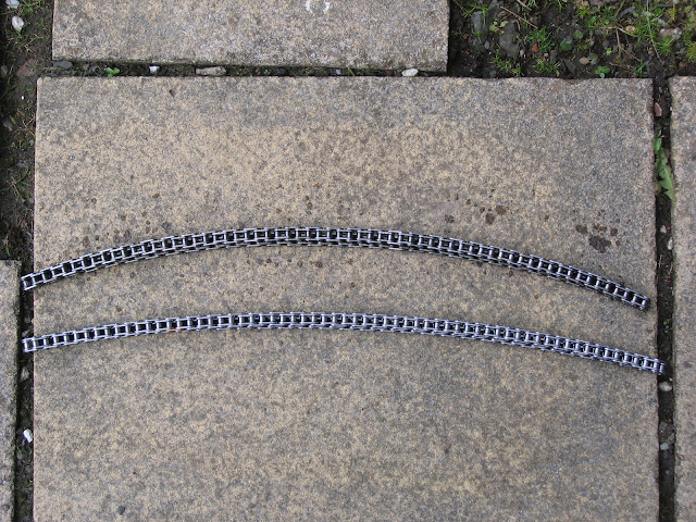
The old one is the top one.
In order to be able to change the chain you had to remove the two gear wheels fitted to the cam shafts. For this (and further movement of the crankshaft) I fitted a ratchet wrench with an 8 mm allan key bit into the end of the shaft. Before removing the gear wheels I moved the indicator holes in the wheels to line up with the seam of the cylinder cover as per book.
In the UK you can hire some BMW tools from the UK BMW Club. Great service as some of these tools are not easy to come by and would see little use anyway.

In the picture you see the tools they can provide. The Hall sensor test box (9V battery inside LED indication), the sparkplug extension bit; basically a part to allow fitting of a dial gauge ouside of the spark plug lead pocket and a dial gauge.
Below you see the extender fitted

The new chain and 'modified' tensioner were fitted after counting the links; please look at the forum for further info! The timing chain cover was fitted, after clarifying if the new seal was to be soaked in oil or not (Not - thanks Forum!) BTW, a little bottle of Tylenol will be a perfect size for a guide for the new seal!

The ratchet was fitted, so we could turn the engine over easily again.
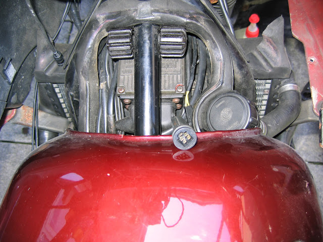
In order to be able to use the timing control box you need to connect it to the connector of the Hall sensors. This connector lies under the tank on the right hand side, connected to a plug that goes into the injection computer plug cover. With the tank pulled back its easy to get at. In the picture below you can see the plug against the tank
Below we have everything hooked up/fitted and ready to start the job. In order to understand how the hall sensor works a bit of theory (sorry ) - BTW TDC means Top Dead Centre which is the point where the piston is at the top of the stroke/movement.
Our bikes have electronic ignition and fuel injection. In order for the engine to function it requires the right amount of fuel to be injected and the ignition to start at the right time. Lots of things to get right then! These are processes that are to be timed correctly with the revolutions of the engine and the way this signal is made available is through the Hall sensors. Sounds magical, but they are simplistically an on/off switch that switches when a bit of steel is put close to them or taken away. In the first picture you can see the sensor ring on top of the engine with the two opposing sensors (K100 - 4cyl 180 degr.). On the forward end of the crankshaft is a cup bolted that has an opening in its side, which is at the height of the sensors so that with every revolution of the shaft this opening (a little 'window') passes in front of the sensor, making it switch. This switching is used as a revolutions signal and to initiate the sparking of the spark plugs. There are two sensors and one window in the cup, so there will be two 'pulses' (on/off/on switches) per revolution of the crankshaft. Still with me here??
Gets worse - They way an engine works is by burning fuel as you know. How it does that is important for the efficiency of the engine. I won't go into air/fuel mixture here, but I think all appreciate that you need to get the mixture right for proper burning (and thus energy generation) and emmision control.
To make the engine turn over you need to generate a pressure in the cylinder to push the piston away. You do this by burning the fuel, whereby the fuel is changed from a liquid (dense) form into a gas (expanded) form. You are generating a pressure build up every time you burn the fuel in the cylinder, which pushes the piston away and turns the engine over. However the speed that the pressure is generated over (the 'burning time' of the fuel) and the volume increase in the cylinder, once the piston starts moving away from TDC, need to be in sync. Basically meaning that you need to keep the pressure fairly high even when the piston is already halfway down the bore. This is controlled with the amount of fuel injected and the time it is ignited. The liquid fuel as atomised (lots of little drops) by the injectors doesn't burn instantanious when ignited. Its almost as if every drop needs to ignite the next one after the first ones are started by the spark plug. Its almost as if your looking at the rings in a pond if you drop a stone in it. This also means that you don't have instantanious pressure. Now we are getting to the reason of this little bit! This means that, in order that you have a correct pressure build up over the stroke of the piston you need to ignite the fuel before (!) the piston is in TDC. To make sure it happens at the right time (per book 6 degrees or .24mm before TDC) we need to put the piston at the right position of this .24mm before TDC and check that the indicator box light switches off at that precise moment.
Long story short; we have to set the ignition point at .24mm before TDC on cylinder No.1. We do this by means of the dial gauge and an extended pin, where the piston will push the pin out until it reaches TDC, before it is pushed back in once the piston moves past TDC. Further we have the timing box which will indicate to us when the hall sensor switches. Adjustment (if required) is done by rotating the sensor carrier disk clockwise or counter clockwise.
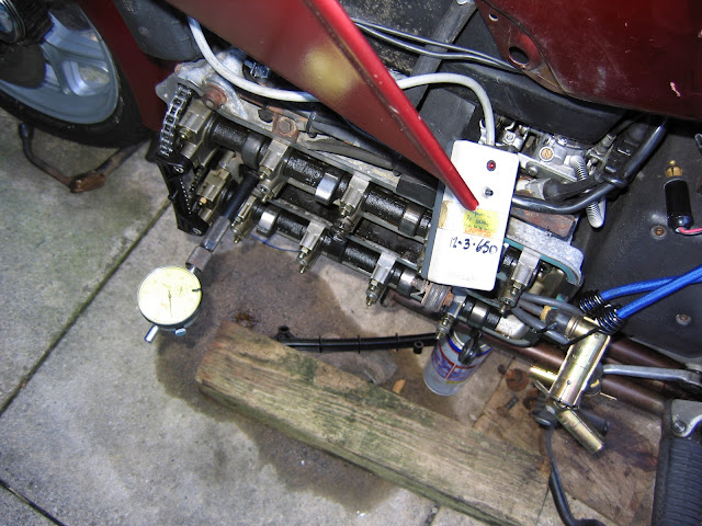
Found TDC and adjusted the dial to show '0'. The instruction book tells us that the initial setting should be 6 degrees before TDC, which computes to 0.24mm. You can see the black indicator adjusted to that.
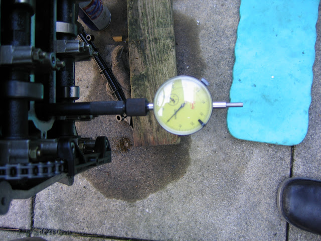
OK, found the right position of the piston (.24 mm before TDC). Whilst looking at the indicator box meantime (Man can multitask!!) I noted that the light didn't switch at the right time.
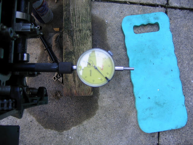
In order to see if the sensor ring had to be adjusted cw or ccw I had to find the point where the sensor switched and then check the dial.

After a bit of playing around I found the right spot and fixed the sensor plate. I turned the engine over a few times in normal direction to make sure it was set right and job done!!
Possibly you have read the manual where it says to initially set the sensor plate with its hole lined up with the recess in the housing. I added the below picture to show you how the bike is set now so that you, with a simple 12V LED, can quickly check the timing. This is what you should see when the piston is .24mm before TDC. In other posts examples have been given how to make a timing check box, where CF's one with a 12V LED is very simple and possible to rig up road side with a bit of wire and the LED (I have a bit of wire with a 12V LED on the bike; easy for fault finding).

If you want to know a bit more about the operation of a 4-stroke engine please have a look HERE, where you'll find a better visual presentation than my piece above.
Further, if you have any comments, remarks, critisism on the above please let me know and I'll change/add to make sure it adds some value.
I decided to take of both side covers to have a quick look at my rivets (6 rivet output shaft
 ) as well.
I sprayed the cams with some dry teflon lube to ensure easy movement over the valve plates (I checked/adjusted clearance as well), tied the spark plug leads out of the way and took the spark plugs out (to be renewed) to prevent pressure build up whilst turning the engine over.
After I had removed the chain I compared old with new. One can measure length or measure difference between 'pulled' and 'pushed' links, but bending the overal chain slightly showed a good reason to renew.
The old one is the top one.
In order to be able to change the chain you had to remove the two gear wheels fitted to the cam shafts. For this (and further movement of the crankshaft) I fitted a ratchet wrench with an 8 mm allan key bit into the end of the shaft. Before removing the gear wheels I moved the indicator holes in the wheels to line up with the seam of the cylinder cover as per book.
In the UK you can hire some BMW tools from the UK BMW Club. Great service as some of these tools are not easy to come by and would see little use anyway.

In the picture you see the tools they can provide. The Hall sensor test box (9V battery inside LED indication), the sparkplug extension bit; basically a part to allow fitting of a dial gauge ouside of the spark plug lead pocket and a dial gauge.
Below you see the extender fitted
The new chain and 'modified' tensioner were fitted after counting the links; please look at the forum for further info! The timing chain cover was fitted, after clarifying if the new seal was to be soaked in oil or not (Not - thanks Forum!) BTW, a little bottle of Tylenol will be a perfect size for a guide for the new seal!
The ratchet was fitted, so we could turn the engine over easily again.
In order to be able to use the timing control box you need to connect it to the connector of the Hall sensors. This connector lies under the tank on the right hand side, connected to a plug that goes into the injection computer plug cover. With the tank pulled back its easy to get at. In the picture below you can see the plug against the tank
Below we have everything hooked up/fitted and ready to start the job. In order to understand how the hall sensor works a bit of theory (sorry
Our bikes have electronic ignition and fuel injection. In order for the engine to function it requires the right amount of fuel to be injected and the ignition to start at the right time. Lots of things to get right then! These are processes that are to be timed correctly with the revolutions of the engine and the way this signal is made available is through the Hall sensors. Sounds magical, but they are simplistically an on/off switch that switches when a bit of steel is put close to them or taken away. In the first picture you can see the sensor ring on top of the engine with the two opposing sensors (K100 - 4cyl 180 degr.). On the forward end of the crankshaft is a cup bolted that has an opening in its side, which is at the height of the sensors so that with every revolution of the shaft this opening (a little 'window') passes in front of the sensor, making it switch. This switching is used as a revolutions signal and to initiate the sparking of the spark plugs. There are two sensors and one window in the cup, so there will be two 'pulses' (on/off/on switches) per revolution of the crankshaft.
 Still with me here??
Gets worse
To make the engine turn over you need to generate a pressure in the cylinder to push the piston away. You do this by burning the fuel, whereby the fuel is changed from a liquid (dense) form into a gas (expanded) form. You are generating a pressure build up every time you burn the fuel in the cylinder, which pushes the piston away and turns the engine over. However the speed that the pressure is generated over (the 'burning time' of the fuel) and the volume increase in the cylinder, once the piston starts moving away from TDC, need to be in sync. Basically meaning that you need to keep the pressure fairly high even when the piston is already halfway down the bore. This is controlled with the amount of fuel injected and the time it is ignited. The liquid fuel as atomised (lots of little drops) by the injectors doesn't burn instantanious when ignited. Its almost as if every drop needs to ignite the next one after the first ones are started by the spark plug. Its almost as if your looking at the rings in a pond if you drop a stone in it. This also means that you don't have instantanious pressure. Now we are getting to the reason of this little bit! This means that, in order that you have a correct pressure build up over the stroke of the piston you need to ignite the fuel before (!) the piston is in TDC. To make sure it happens at the right time (per book 6 degrees or .24mm before TDC) we need to put the piston at the right position of this .24mm before TDC and check that the indicator box light switches off at that precise moment.
Long story short; we have to set the ignition point at .24mm before TDC on cylinder No.1. We do this by means of the dial gauge and an extended pin, where the piston will push the pin out until it reaches TDC, before it is pushed back in once the piston moves past TDC. Further we have the timing box which will indicate to us when the hall sensor switches. Adjustment (if required) is done by rotating the sensor carrier disk clockwise or counter clockwise.
Found TDC and adjusted the dial to show '0'. The instruction book tells us that the initial setting should be 6 degrees before TDC, which computes to 0.24mm. You can see the black indicator adjusted to that.
OK, found the right position of the piston (.24 mm before TDC). Whilst looking at the indicator box meantime (Man can multitask!!) I noted that the light didn't switch at the right time.
In order to see if the sensor ring had to be adjusted cw or ccw I had to find the point where the sensor switched and then check the dial.
After a bit of playing around I found the right spot and fixed the sensor plate. I turned the engine over a few times in normal direction to make sure it was set right and job done!!
Possibly you have read the manual where it says to initially set the sensor plate with its hole lined up with the recess in the housing. I added the below picture to show you how the bike is set now so that you, with a simple 12V LED, can quickly check the timing. This is what you should see when the piston is .24mm before TDC. In other posts examples have been given how to make a timing check box, where CF's one with a 12V LED is very simple and possible to rig up road side with a bit of wire and the LED (I have a bit of wire with a 12V LED on the bike; easy for fault finding).
If you want to know a bit more about the operation of a 4-stroke engine please have a look HERE, where you'll find a better visual presentation than my piece above.
Further, if you have any comments, remarks, critisism on the above please let me know and I'll change/add to make sure it adds some value.
Last edited by ReneZ on Tue May 29, 2012 10:06 am; edited 3 times in total
__________________________________________________
Greetings from
Rene
BMW K100 - 1985 (0030029) Scotland

BMW K1200GT - 2003 (ZK01223) Florida
BMW K1200GT - 2004 (ZK27240) Australia


