BMW K bikes (Bricks)


You are not connected. Please login or register

View previous topic View next topic Go down  Message [Page 1 of 1]


1Back to top Go down   How to get a cheap eBay Speedo to work Empty How to get a cheap eBay Speedo to work Fri Jan 13, 2017 12:19 am

Jacod

Jacod
active member
active member
I recently put on one of those cheap eBay speedos on my K100 and to my surprise I got it all to work, I even used the OEM speed sensor. I did so by trawling through various forums for hours on end. Especially this one and the MotoBrick forum. 

I haven’t got the gear position indicator to work yet. I have to start it with the clutch in and the N light doesn’t illuminate because of this. I am hoping to use one of RBM’s TGPI boards for this (let me know if it will work? Cheers)


To hopefully save any future tin bums some time I have explained below how I managed to get the speedo to work. 


First of all there seems to be two types of these cheap eBay speedos on the market that have differently colour coded wires so I’m not going to put up what colour went to where. The basic wire up is pretty simple you just need to decode their useless instructions. 


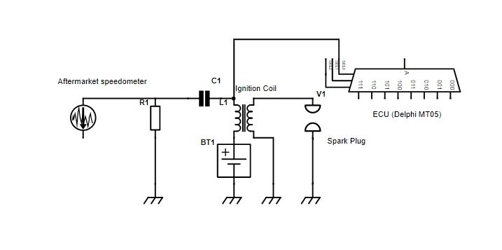
Unfortunately you can’t wire the tacho strait into these cheap speedometers and you need to make a filter using a capacitor and a resistor as mentioned on another thread https://www.k100-forum.com/t8232-electrical-trouble-mounting-aftermarket-digital-speedo in this forum. The circuit mentioned in that thread didn’t work for me at first, so I replaced the mentioned capacitor with a 10uf 23v polarised capacitor. Other than that the circuit was the same. 

I also needed to change my settings to 4 cylinders in the ‘hidden settings’ for this to work (see how below)How to get a cheap eBay Speedo to work Screen10

To access the hidden settings press and hold the button on the back for a while before you turn the ignition on, continue holding once you have turned the igntion on until the ‘hidden menu’ comes up. Short press the button to make a change. Wait without pressing anything for the flashing number to cycle to the next 
Press and hold the button again to cycle through the settings and save any changes. 

For my speedo the hidden menu items corresponded to the following:
Menu 1 is the circumference of the rear wheel (tyre) in mm ( I played around with mine, it is now quite accurate when set to 2060) you can calibrate your speedo using a 50 or 60hz soldering iron turned on and placed close to your speed sensor pick up as mentioned in another thread. To change it simply reduce or increase the circumference size accordingly.
Menu 2 is the number of magnetic sensors you have attached to your wheel (set this to 6 if using OEM speedo sensor).
Menu 3 is the number of cylinders (set to 4)
Menu 4... I'm not sure but it could be the resistance setting for the fuel gauge (didn’t change it)
Menu 5 is to reset the Odometer (not trip meter)

https://www.youtube.com/watch?v=NSXYYkXvISw shows you how to access the hidden menu. 


The other thing that won’t work off the bat is the fuel gauge. You will need to wire your aftermarket speedometer fuel gauge wire to the yellow wire of your accessories connector under the tank. Not all models have this accessory connector and if yours doesn’t you're probably outta luck. For me, after wiring it to this yellow wire it worked perfectly without changing any of the ‘hidden’ settings. 


To get the speedo to work using the OEM sensor you can use the motometer board trick as mentioned in another thread https://www.motobrick.com/index.php/topic,8017.msg59081.html#msg59081. To wire it up follow RBM’s instructions: 

BE - (an input) goes to Yellow wire coming from the sensor in the rear drive
"-" - goes to ground.  Also connect the Brown wire from the sensor in the rear drive to this terminal (this means there are two ground wires connected to this)
BA - (an output) goes to the speedo input on your gauge
"+" - goes to a source of switched +12V power
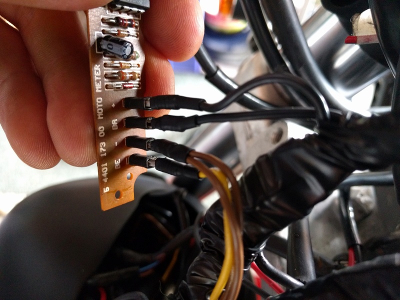
How to get a cheap eBay Speedo to work Img_2013

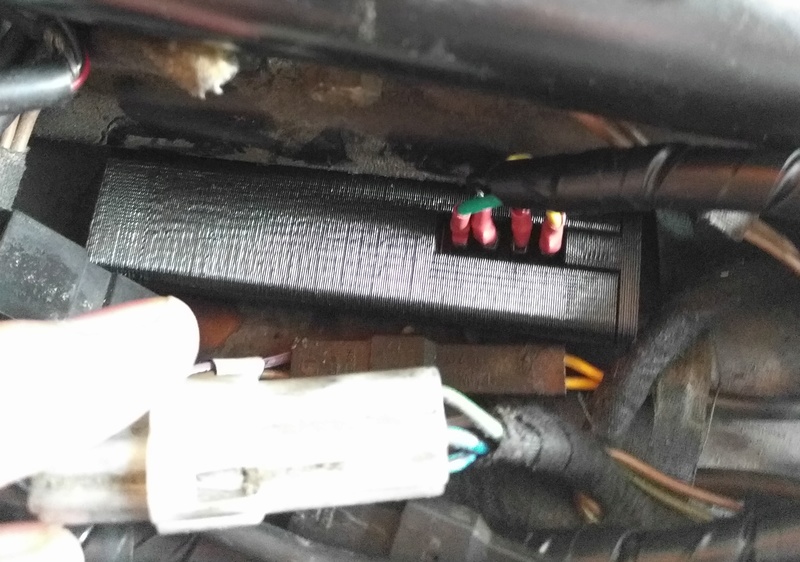
I also quickly designed and 3D printed a case to connect this which I fitted under the tank which works nicely. See pictures
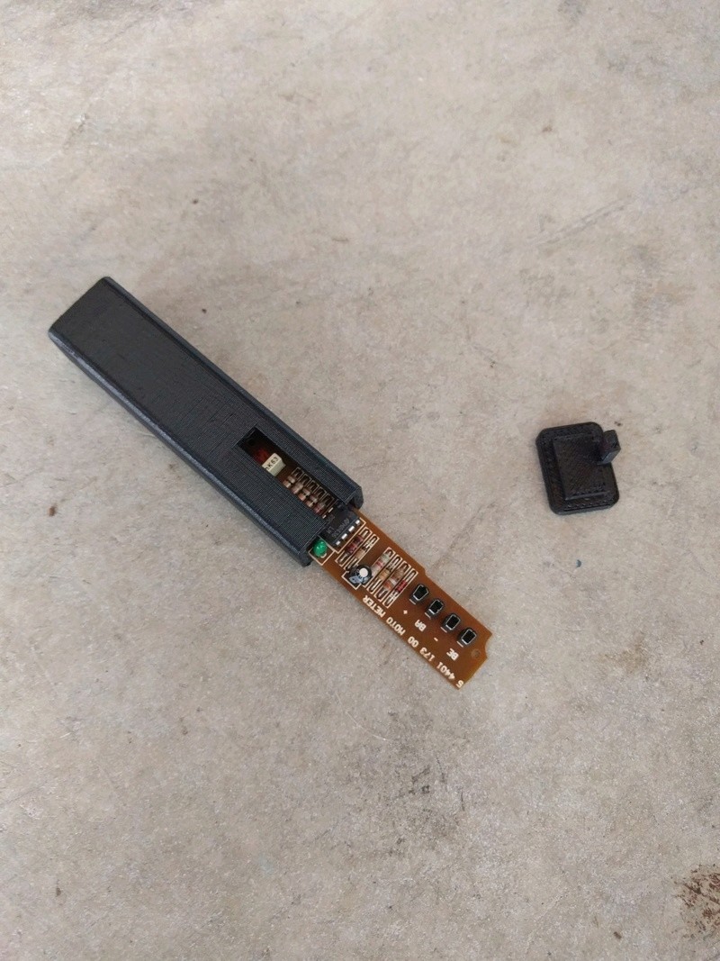
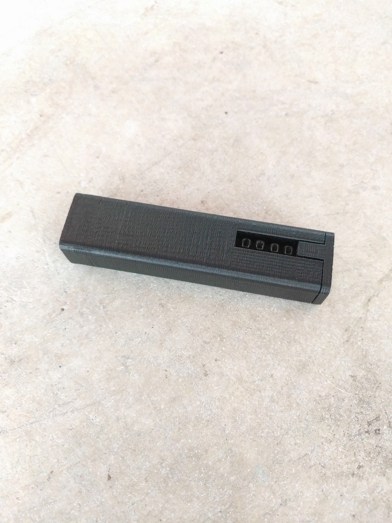
How to get a cheap eBay Speedo to work Img_2012How to get a cheap eBay Speedo to work Img_2011How to get a cheap eBay Speedo to work Img_2010


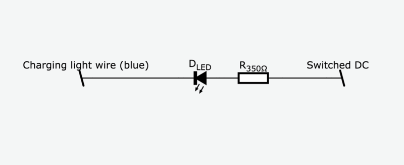
Things got a little tricky when you want to add some extra warning lights. (A side note; you need a battery indicator light for the battery to charge…) Some of the wires for the warning lights are negatively polarised (see https://docs.google.com/spreadsheets/d/1qF1-ECuyT1TT5L72CG9wYYxpeZr1PPonn0LED-_cvD4/edit#gid=0 ) meaning if you wired them up like you think you would a normal circuit they won’t work. The trick to get these ones to work is to wire a good source of positive switched DC to the anode, and connect cathode to the corresponding wire.
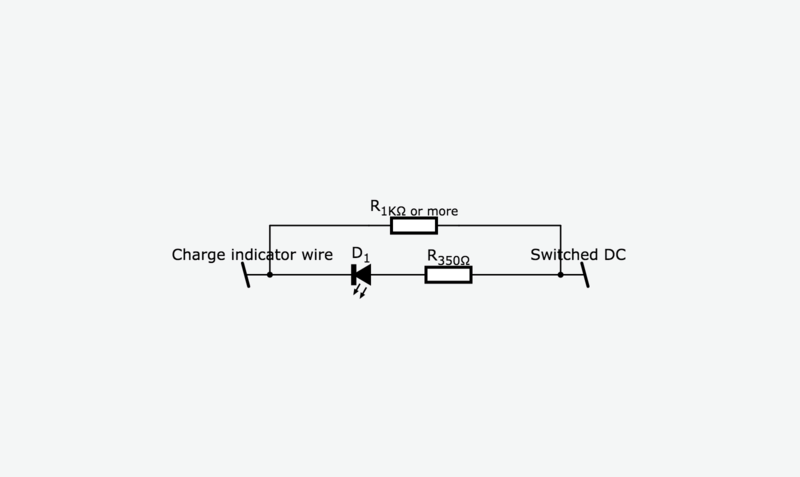
I used a very basic LED and resistor combo to get this to work. And yes the battery charges.  See below

How to get a cheap eBay Speedo to work Screen11

Check out my video of it working on YouTube

p.p1 {margin: 0.0px 0.0px 0.0px 0.0px; font: 12.0px Helvetica} p.p2 {margin: 0.0px 0.0px 0.0px 0.0px; font: 12.0px Helvetica; min-height: 14.0px} p.p3 {margin: 0.0px 0.0px 0.0px 0.0px; line-height: 16.0px; font: 12.0px Helvetica} p.p4 {margin: 0.0px 0.0px 0.0px 0.0px; line-height: 16.0px; font: 12.0px Helvetica; min-height: 14.0px}


nods

nods
Silver member
Silver member
Thanks a lot Jacod, very helpful!


__________________________________________________
Chassis number0025951
Vehicle code0504
SeriesK589
ModelK 100 RT 84 (0504 ( 0505 )
Body typeK 100 RT 84 (0504
Catalog modelECE
Production date1985 / 01
Engine0514)
Transmission
Steering
CatalyzerNONE
    

nods

nods
Silver member
Silver member
Jacod wrote:

Things got a little tricky when you want to add some extra warning lights. (A side note; you need a battery indicator light for the battery to charge…)

Hi Jacod, I'm after a little more info on this point, if you don't mind.

I could have sworn I'd read at some point about needing an incandescent light to make something work but never found that reference again.

What does the above mean?  I've removed the original instrument cluster and will only have a few LED warning/indicator lights on the new speedo.  Do I need to have an old school bulb somewhere for the charging circuit to work?

Cheers for any info,
Nods


__________________________________________________
Chassis number0025951
Vehicle code0504
SeriesK589
ModelK 100 RT 84 (0504 ( 0505 )
Body typeK 100 RT 84 (0504
Catalog modelECE
Production date1985 / 01
Engine0514)
Transmission
Steering
CatalyzerNONE
    

Dai

Dai
Life time member
Life time member
Nice job!


__________________________________________________
1983 K100 naked upgraded to K100LT spec after spending time as an RS and an RT
1987 K100RT
Others...
1978 Moto Guzzi 850-T3, 1979 Moto Guzzi 850-T3 California,1993 Moto Guzzi 1100ie California
2020 Royal Enfield Bullet 500
    

mike d

avatar
Life time member
Life time member
nods wrote:
Jacod wrote:

Things got a little tricky when you want to add some extra warning lights. (A side note; you need a battery indicator light for the battery to charge…)

Hi Jacod, I'm after a little more info on this point, if you don't mind.

I could have sworn I'd read at some point about needing an incandescent light to make something work but never found that reference again.

What does the above mean?  I've removed the original instrument cluster and will only have a few LED warning/indicator lights on the new speedo.  Do I need to have an old school bulb somewhere for the charging circuit to work?


Nods

Generally you would require a suitable wattage bulb to 'excite' the alternator. This means to enable the charging circuit to be kick started.

Led bulbs do not provide the required resistance to trigger this excitation, although it is sometimes found that revving the bike engine above say 3000 revs will produce the same effect.

Mike


Last edited by mike d on Sun Jan 15, 2017 8:05 pm; edited 1 time in total (Reason for editing : erasing crap editing!)


nods

nods
Silver member
Silver member
mike d wrote:
nods wrote:
Jacod wrote:

Things got a little tricky when you want to add some extra warning lights. (A side note; you need a battery indicator light for the battery to charge…)

Hi Jacod, I'm after a little more info on this point, if you don't mind.

I could have sworn I'd read at some point about needing an incandescent light to make something work but never found that reference again.

What does the above mean?  I've removed the original instrument cluster and will only have a few LED warning/indicator lights on the new speedo.  Do I need to have an old school bulb somewhere for the charging circuit to work?


Nods

Generally you would require a suitable wattage bulb to 'excite' the alternator. This means to enable the charging circuit to be kick started.

Led bulbs do not provide the required resistance to trigger this excitation, although it is sometimes found that revving the bike engine above say 3000 revs will produce the same effect.

Mike
Thank you Mike.  Does this mean a small resistor with a similar resistance to a light bulb would do the same job?


__________________________________________________
Chassis number0025951
Vehicle code0504
SeriesK589
ModelK 100 RT 84 (0504 ( 0505 )
Body typeK 100 RT 84 (0504
Catalog modelECE
Production date1985 / 01
Engine0514)
Transmission
Steering
CatalyzerNONE
    

Rick G

Rick G
admin
admin
All you need is a 12V 3W light bulb


__________________________________________________
"Man sacrifices his health in order to make money.
Then he sacrifices money to recuperate his health.
And then he is so anxious about the future that he does not enjoy the present; the result being that he does not live in the present or the future; he lives as if he is never going to die, and then dies having never really lived."   Dalai Lama


Bikes 1999 K1100 LT with a Big Block 1200
    

Jacod

Jacod
active member
active member
Nods.

I too was under the impression that I would need to add a resistor to simulate the same load as the bulb would in the original circuit. I had read this on various other threads too. However, when I was wiring it up I thought I would give it a shot with just the LED and the 0.5w 350Ω resistor (as wired up in the diagram) to my absolute surprise it worked. The battery light comes on when the battery is low, and it turns off when it's charging. I double checked it was charging by putting a multimeter across the battery terminals and revved the bike a bit... and sure enough it charges. 

Not entirely sure why but it works for me.


Dai

Dai
Life time member
Life time member
Almost certainly residual magnetism. I have one alternator here that switches on at about 1500rpm and stays on at tickover with just an LED (no resistor) as the indicator. As it's a '12 volt' LED there's some form of resistor built into it which will help but I've no idea what rating it is.


__________________________________________________
1983 K100 naked upgraded to K100LT spec after spending time as an RS and an RT
1987 K100RT
Others...
1978 Moto Guzzi 850-T3, 1979 Moto Guzzi 850-T3 California,1993 Moto Guzzi 1100ie California
2020 Royal Enfield Bullet 500
    

nods

nods
Silver member
Silver member
Thanks everyone, doesn't sound too daunting now.

Cheers,
Nods


__________________________________________________
Chassis number0025951
Vehicle code0504
SeriesK589
ModelK 100 RT 84 (0504 ( 0505 )
Body typeK 100 RT 84 (0504
Catalog modelECE
Production date1985 / 01
Engine0514)
Transmission
Steering
CatalyzerNONE
    

Jacod

Jacod
active member
active member


nods

nods
Silver member
Silver member
Jacod wrote:Link to motometer case http://www.thingiverse.com/thing:2042596
Very cool, thanks mate. I've no experience with 3D printing - do I download the plan and take somewhere that has a 3D printer?


__________________________________________________
Chassis number0025951
Vehicle code0504
SeriesK589
ModelK 100 RT 84 (0504 ( 0505 )
Body typeK 100 RT 84 (0504
Catalog modelECE
Production date1985 / 01
Engine0514)
Transmission
Steering
CatalyzerNONE
    

Jacod

Jacod
active member
active member
nods wrote:Very cool, thanks mate. I've no experience with 3D printing - do I download the plan and take somewhere that has a 3D printer?
I guess, yeah. I'd just google it to see who has one in your local area. I'm lucky enough to have access to one and get to use them on a daily basis. Perhaps you could try your local library  I've heard some are getting them in now.


dariok1

dariok1
New member
New member
How did U make the trim around the gauge with the battery, choke, etc symbols stamped ??


Jacod

Jacod
active member
active member
dariok1 wrote:How did U make the trim around the gauge with the battery, choke, etc symbols stamped ??
Aluminium, a Bandsaw, a Holesaw, and a dremel. 

Also, I should mention after riding the bike a bit the LED charge indicator light blew. I'm guessing the LED didn't like the charge coming back up from the alternator when the engine was at high revs. It was an easy fix though. I just put a new LED in the same way as last time, but this time I added second resistor that had a higher resistance the the accumulative total of the LED and the initial resistor. This means that when current is flowing from the battery to the charge indicator LED it lights up because the LED circuit has less resistance than the second short circuiting resistor. However, when the current is reversed flowing from the alternator; the LED, being a diode doesn't let the current flow through it so the current flows through the second resistor. If you don't know what I mean you need to google how an alternator works. How to get a cheap eBay Speedo to work Screen10

Also that Google Sheets I linked in the initial post showing the polarity of the wires going to the speedo neglects to mention that the Oil Pressure light is also negatively polarised so you will need to wire it the same way as I suggested you wire the other negatively polarised lights. 

Hope this makes sense


16Back to top Go down   How to get a cheap eBay Speedo to work Empty Further detail Wed May 10, 2017 2:28 am

Jacod

Jacod
active member
active member
Further detail on how I finished wiring it up available here https://www.k100-forum.com/t12259-an-alternative-way-to-get-the-gear-position-indicator-to-work-on-an-aftermarket-speedo


17Back to top Go down   How to get a cheap eBay Speedo to work Empty GREAT info Tue Oct 17, 2017 2:32 pm

Gr-Racing

Gr-Racing
active member
active member
Great info thanks,

I got it all wire but i still cant get the RPM to work for me i follow your wiring diagram i think but still nada
Can you give me a hand 

can you post a pic of how you did the capacitor and resistor

Thanks


Guest

avatar
Guest
Jacod wrote:...
The other thing that won’t work off the bat is the fuel gauge. You will need to wire your aftermarket speedometer fuel gauge wire to the yellow wire of your accessories connector under the tank. Not all models have this accessory connector and if yours doesn’t you're probably outta luck. For me, after wiring it to this yellow wire it worked perfectly without changing any of the ‘hidden’ settings. 
Hi Jacod, 
thanks for sharing this.
I have tried to connect to the fuel gauge as you suggested, but it hasn't worked  Sad Not sure what I'm doing wrong.
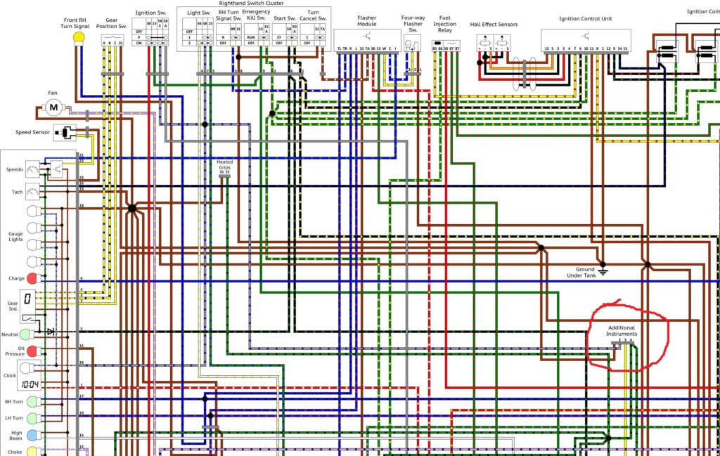
I have tried to connect it to the yellow wire on the "additional instruments" connector under the fuel tank (circled in red below):
How to get a cheap eBay Speedo to work Additi10
Can you please confirm if this is the right connector?

Thanks.


Suzi Q

Suzi Q
Life time member
Life time member
Yellow is correct for the fuel level sender - assuming you have the float type sender unit in the tank.
The OE sender should read 0 Ohm when full, and 100 Ohms when empty - measuring the resistance between the yellow wire and ground. It's a good idea to test this as part of your troubleshooting.
The aftermarket instruments can be programmed to either '100 Ohms empty/0 Ohms full' or '0 Ohms empty/100 Ohms full'. Even if they aren't programmed correctly,hey should still work, albeit backwards.


__________________________________________________
Sometimes I'm not really Suzi Quatro.
    

Guest

avatar
Guest
Thanks Suzi.
I will try to do these measurements and provide an update once done.


robmack

robmack
Life time member
Life time member
The motorcycle gauges off Ebay are based on the same internals (just different casing and visual details).  the fuel indicator on these gauges are oriented around senders used in Japanese bikes which have about 100 Ohms full tank and about 0 ohms empty tank.  BMW K100 sender is opposite to this with 0 ohm about for full tank and 100 ohms or about for empty tank.  To get this to work properly you'll have to reverse the sender.  I detail this in my Page Messing with the In-tank Fuel Sender


Aftermarket gauge documentation

http://k75retro.blogspot.ca/
    

Guest

avatar
Guest
Update on my issue:

I have measured the resistance of the fuel sender, and as Rob mentioned was around 111 ohms - empty tank, and 16 ohms - full tank.
I have tried to change the settings of the aftermarket speedo to align them to the BMW sender, but I haven't had much luck.
Has anybody done that successfully? 

Thanks.


Suzi Q

Suzi Q
Life time member
Life time member
Yes.
To enter programming mode you have to press and hold the rear button soon after power on - whilst the unit is still performing its startup routine/display.
Once you are in programming mode, a long press-until-the-number-changes moves it through the various programming modes - the number of whichever mode you are in is indicated in the speedometer section of the display. Mode number 4 is the programming mode for the fuel gauge. Quick pressing the button will then alternate between either a '2' or a '3' in the mileage section of the display. '3' is correct for 0 Ohms full/100 Ohms empty.


__________________________________________________
Sometimes I'm not really Suzi Quatro.
    

Guest

avatar
Guest
I have managed to get the fuel gauge on the aftermarket speedo to work. Thanks for all the support!
However, I'm now facing a new issue!  Sad
I have tried to get the tachometer to work as well. I followed the instructions provided by Jacod, so I connected a resistor and a capacitor as follows: 

How to get a cheap eBay Speedo to work Circui11

The tachometer needle still doesn't move at all on the speedo.
Am I doing something wrong? 

Thanks in advance.


Suzi Q

Suzi Q
Life time member
Life time member
I can only paste the below post - from a thread in  a galaxy far, far away - that sort of explains how I overcame this problem. Good luck  Shocked

Well, I tried the various filters for the tacho signal  (the blue/black 'switched' wire from the Motronic to coil 1 primary that the OE instruments use) to try and get the ebay tacho of doom to work. Best I could get was an intermittent response. There are some great posts on this and other forums that educate you into what's going off but, basically, the raw voltage from the coil 1 primary just isn't good enough for the cheapo tacho to read.

I first tried a filter consisting of a capacitor placed inline in the blue/black wire from the Motronic/coil primary to the tacho. This wire is sourced from the Motronic and normally rests at 12v and drops to 0v before immediately rising back to 12v every time a spark is required. The inrush of 12v causes a bit of a peak, well above 12v in the primary, which translates into about a gazillion volts in the secondary, hence the spark. The peak doesn't just build up in the coil primary winding, it also feeds back into the blue/black wire.

This was all evident in the oscilloscope trace. Unfortunately, although it was plain to see on the scope, the tacho wasn't reading what was going off in the blue/black wire. This was because the blue black wire (doing such a good job) lives in ground zero (electronically speaking) and was suffering from voltage trauma. 

By putting the above capacitor in the blue/black wire from the coil to the tacho, this took away the baseline 'resting' 12v after the capacitor (capacitors don't flow steady currents), and tying the same wire post-capacitor to earth via a 100Kohm resistor meant that, between capacitor discharges, the wire sank to 0v. This set up did get some response from the tacho, but there was a lot of fluctuation.

Which is when the weird thing happened. This was when I used a multimeter to measure the voltage frequency of this wire (the blue/black wire after the capacitor into the tacho, also connected to earth via the 100kohm resistor). Every time I connected the multimeter to the blue/black wire (the tacho input) the tacho started reading properly.

Straight away, option 1 arose. This involved permanently soldering/gaffer taping the multimeter to the bike. I did not discount this, but I did think it might be worthwhile finding an alternative.

Hence the oscilloscope. This is a 1976 vintage, sourced from ebay for a NASA-budget twenty five quid. This piece of history-in-action showed that everytime the multimeter was connected, the biggest voltage spike on the blue/black wire got shaved off. This showed me 2 things: 1; unlike me, multimeter designers know how to do stuff, and 2; I needed to shave of some of the voltage spike.

Step forward Mr Diode. I connected this between the blue/black wire, and a nearby 12v, in the simplistic hope that it would flow anything above 12v on the blue/black wire to...somewhere.

And the f****er works!

There's no likelihood that this electronic breakthrough is in any danger of being celebrated. I am not the smartest person around here, but I do suspect that what I have achieved is the electronic equivalent of using a rusty angle iron offcut as a headlamp bracket, compared with a properly designed and machine aluminium offering. It's taught me to have a bit more admiration for the guys who ride bikes with angle iron brackets....


__________________________________________________
Sometimes I'm not really Suzi Quatro.
    

Suzi Q

Suzi Q
Life time member
Life time member
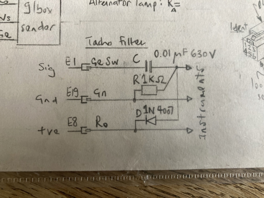
Sorry for the above drivel - I've found my wiring diagram showing the tacho filter that I ended up using. A bit of explanation; E1, E19, E8 are the the names I gave on the white 20-way multipin connector that plugs into the rear of the instruments. So ignore them! The diagram just shows how you connect the three components (capacitor, resistor, diode) across the three relevant wires going into the instruments (tacho signal, ground, switched positive). As you've already identified, you're working with the black/blue wire from coil 1 for your tacho signal.

How to get a cheap eBay Speedo to work Img_4912

The diode is just there to lose anything above 12v on the black/blue signal wire (which gets a bit spiky with what's going off in the coil its connected to) I think it's probably these spikes that make the signal hard for the instruments to read. Anyway, this filter has worked fine on two different bikes so far.


__________________________________________________
Sometimes I'm not really Suzi Quatro.
    

robmack

robmack
Life time member
Life time member
Your resistor - capacitor circuit is wrong.  The circuit Suzi Q posted is right.  The cap is in series with the tach signal, and the resistor goes from the output of the cap to ground.  The cap is a ceramic type of about 0.1 uF and the resistor is about 33K, 5%, 1/2 watt.  The circuit is R1 - C1 shown below:

How to get a cheap eBay Speedo to work 5814973000_1576496012

http://k75retro.blogspot.ca/
    

Guest

avatar
Guest
Thanks Rob / Suzi.
If I understand correctly the following circuit should work:
How to get a cheap eBay Speedo to work Circui12
Can you please confirm?
Sorry but saying that my knowledge of electronics are very basic it's an overestimation! Smile


Thanks


robmack

robmack
Life time member
Life time member
The circuit looks correct. If the clamping diode works for Suzi Q, then include it. I think it is optional.

http://k75retro.blogspot.ca/
    

Guest

avatar
Guest
Thanks for the quick reply.
I will try that and keep you posted.


Suzi Q

Suzi Q
Life time member
Life time member
Without the diode, the tacho worked but was a bit erratic. When I used the multimeter to check the frequency on the black/blue wire, the tacho suddenly worked fine. Head scratching. The oscilloscope then showed that, with the multimeter connected, the signal on the black/blue wire was kept down to 12v, whereas without the multimeter it flew much higher than that - presumably because it was getting some electrical mess from the coil. It seems that the tacho can't really cope with a poor quality signal without some help. The diode gets rid of the excess voltage because, by being connected to a good 12 volt wire (i.e. the positive supply to the instruments for instance) it operates like a one-way valve, releasing excess electrical pressure into the the wide blue yonder of the bike's 12v circuit(s) where there is plenty of stuff to dissipate it. That's why Robmack calls it a clamping diode - because he knows what he's talking about.


__________________________________________________
Sometimes I'm not really Suzi Quatro.
    

32Back to top Go down   How to get a cheap eBay Speedo to work Empty Charge light not turning off Wed Oct 04, 2023 6:25 pm

BendK100

BendK100
active member
active member
I have been all over this forum and this post has the most detail I could find about the charge light. I rigged mine with LED and resistor setup described in earlier posts. The LED lights up as soon as I turn on the bike, but it never turns off no matter how high I rev. The voltage on the batter drops from 12.4 to 12.34 after ignition, meaning it's not charging. Is there any easy way to test the alternator without disassembling it?


robmack

robmack
Life time member
Life time member
Toss the LED and replace it with a normal incandescent bulb. Why complicate your life by using a LED for a charge indicator? After the swap, report back your findings.

http://k75retro.blogspot.ca/
    

charlie99

charlie99
VIP
VIP
robmack wrote:Toss the LED and replace it with a normal incandescent bulb.  Why complicate your life by using a LED for a charge indicator?  After the swap, report back your findings.
Indeed     How to get a cheap eBay Speedo to work 112350


__________________________________________________
cheezy grin whilst riding, kinda bloke ....oh the joy !!!! ...... ( brick aviator )

'86 K100 RT..#0090401 ..."Gerty" ( Gertrude Von Clickandshift ) --------O%O
'86 k100 rs.. #######..  "Fred " (f(rame) red ) ( Fredrick leichtundschnell ) - -
bits and pieces from many kind friends across the k100 world ...with many thanks ..
1987 k100rs ########   "Red"  - (red sports rs TWB style )
1989 K100rt #009637   "Black Betty"  (naked rt ala Nigel , now sporting an rs main fairing )
    

Suzi Q

Suzi Q
Life time member
Life time member
It's possible to get confused about the purpose of 'the resistor'*. 

1: you need a resistor in series with the LED because a LED can't cope with more than 3 volts reliably; the series resistor keeps the current through the LED down and enables it to run on 12v. However, a '12V LED' lamp or whatever will have this resistor built in. If you've bought a 12v LED alternator warning lamp for example, you don't need to worry about this resistor - it's built in. If, on the other hand, you've reached for a bare 3v LED from your box of electronic bits, then you'll need one.

2: you also need a resistor in parallel with the LED to keep the current through the alternator up. This is a totally separate issue, and arises because the alternator needs an exciter current of sufficient magnitude to kick it into life. Seems the amount of current required varies amongst the K population out there, and some don't need much at all. When you replace the OE alternator light with a LED, then the lower current that passes through the LED, is sometimes not enough. You overcome this by bypassing some extra current through a suitably sized resistor in parallel with the LED. Kind of defeats the object of using an LED if you ask me, unless your LED warning lamp of choice is heart-breakingly good looking, and worth the effort.

'Pologies if I've done this a bit to death, but it took me a while and the patient assistance of others on this forum to get to grips with this.

*i.e. I did.


__________________________________________________
Sometimes I'm not really Suzi Quatro.
    

36Back to top Go down   How to get a cheap eBay Speedo to work Empty Charge light not turning off Fri Oct 27, 2023 8:44 pm

BendK100

BendK100
active member
active member
I think the issue is not with the resistor. With or without a resistor, the LED bulb barely lit up and nothing happened when connecting a 12V 10W incandescent bulb.
As a test I grounded it to the frame instead of the alternator and it lit up fine. So I think there is a short somewhere in the alternator.
The brushes on the voltage regulator were worn down and within 1mm of serviceable length, so I replaced it with a new one. Service manual said that is the most likely cause of bulb issues, but no change.


Glyn

Glyn
active member
active member
Hi all, I'm fitting an Acewell 080 Speedo on my K1100. I've read everything I can on this site and it seems that the BEP 3.0 and a unit made by Rob Mack can make this task much easier. However as the RM unit is no longer available then there's only the BEP. However, what does this unit actually do? I've already built the 4 relay system and am experimenting with AN741 as a comparator for speed and tacho signal shaping as Suzi Q clearly doesn't want me to ruin the original Speedo unit by removing the Moto panel. So what else does the BEP unit do besides this that I currently have under way?


robmack

robmack
Life time member
Life time member
Glyn wrote:Hi all, I'm fitting an Acewell 080 Speedo on my K1100. I've read everything I can on this site and it seems that the BEP 3.0 and a unit made by Rob Mack can make this task much easier. However as the RM unit is no longer available then there's only the BEP. However, what does this unit actually do? I've already built the 4 relay system and am experimenting with AN741 as a comparator for speed and tacho signal shaping as Suzi Q clearly doesn't want me to ruin the original Speedo unit by removing the Moto panel. So what else does the BEP unit do besides this that I currently have under way?
Hi, I'm still building my TGPI board. There was a time when I was not in a position to build boards but that time has past.

There is also the Marulabs BEP and the Tenet units that recover the functionality you loose when removing the OEM gauge cluster.  The BEP and Tenet boxes are more streamlined to install than my TGPI; those boxes reuse the OEM connectors whereas mine require wired connections to the harness.  The BEP and Tenet cannot drive. gear indicator very well.  I can offer the ability to use an external LED gear indicator if your gauge does not have a built in one or I can drive a builtin gear indicator should your gauge have one.  For the Acewell 080, you'd need an external LED gear indicator because the gear indictor is not builtin.

There are other solutions to address the disappearing OEM gauge cluster using DIY relay based solution to gain start enable and neutral detect.  You can get tachometer readout using a simple wire wrapped around cylinder 1 spark plug wire.  It's nearly impossible to use the OEM road speed sensor in the rear drive without building an amplifier and wave shaper to boost the signal from the VR sensor.

If you are interested in a TGPI board, just send me. message.

http://k75retro.blogspot.ca/
    

Glyn

Glyn
active member
active member
Thanks Rob. I've built the 4 relay unit which works for the Neutral light and the start enable. As suggested by Suzy Q I've purchase an NPN sensor that might fit in the 8mm hole on the rear hub but haven't started to look at that yet. I've seen the proposed CR circuit on these pages to modify the speed signal so may give that a try. Digital instruments have yet to deliver the Ca080 after ordering before Xmas so I can't test much yet. I didn't realise that there was no gear indicator on this instrument. It won't bother me that much to be without it as long as the Neutral light works.


robmack

robmack
Life time member
Life time member
The acewell 080 has a gear indicator but does not have the ability to use the transmission gear switch to read the currently selected gear from the vehicle. Instead you teach the gauge to calculate the gear based on rpm and speed. It could work quite well but I have no experience with this feature.

http://k75retro.blogspot.ca/
    

Sponsored content


View previous topic View next topic Back to top  Message [Page 1 of 1]

Permissions in this forum:
You cannot reply to topics in this forum