1

 REFERENCE: BMW Instrument Cluster schematics Sat Nov 04, 2017 10:13 am
robmack
Life time member

I reverse engineered the LCD Gear Indicator board as part of my project to build a drop-in replacement for the LCD. I then proceeded to reverse engineer some other boards and draw their schematics, as well as collected schematics from other sources and re-interpreted those drawings. The flasher unit schematic is not my work; it is available online. I'll add more as I convert the BMW OEM circuits into schematic drawings.
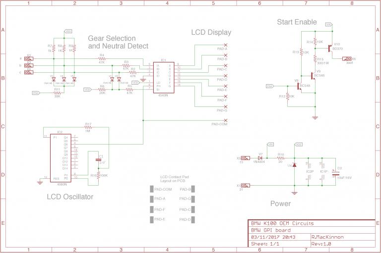
GPI This is the board that is located in the OEM cluster underneath of the Tachometer on the right side, containing the LCD that shows the currently selected gear:


Large Image
Basic Circuit Description
Power is supplied through pin 15 (+12V) and 31 (Ground). A diode, V7, ensures that reversing the polarity of the power will not destroy the components on the board. VIN is fed to the Start Enable circuitry and to the regulator V9. Regulated VDD supplies the chips with power as well as other parts of the circuit.
The TGPI switch connects to A, B and C inputs. Diodes, V3, V4 and V5, form a neutral detect feature that operates the Start Enable circuitry. The three transistors, V8, V9 and V10, creates a +12V signal on the output, LEERL, that drives neutral and the starter relay. Diodes, V1 and V2, detect when the selected gear is higher than 5th and will send a signal to IC1 to blank the LCD display. IC1 decodes the inputs and displays a digit on the LCD via PAD-A through PAD-G.
IC2 is an oscillator that creates a high power signal that powers the LCD. This signal is output on PAD-COM and consists of a 67Hz 100V 50% duty-cycle squarewave.
Speedometer and Odometer
This board is located in the OEM gauge cluster and converts the output from the speed sensor in the final drive into a signal that drives the speedometer servo motor.


Large Image
Tachometer
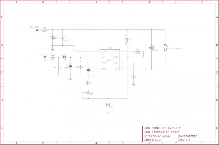
This board is located in the OEM gauge cluster and converts the output from coil #1 into an RPM reading on the tachometer gauge.


Large Image
Early Fuel Level Sensor (4L/7L lights)
This board is located in the OEM gauge cluster for the early K-bikes prior to 1985. The fuel sensor was a pair of thermistors. These devices illuminated a lamp in the OEM gauge cluster that showed when the fuel remaining in the tank was 7 litres and 4 litres. This is an interpretation of a schematic posted by Bert Vogel on K100-forum.


Large Image
Flasher Unit
This schematic was posted online at the K100-forum and I am including it in this collection.


Large Image
Clock
This schematic is of the clock in the OEM dash. To test that all segments of the display are working, press both switches together at the same time.
All segments will light up. When the switches are released, the clock will reset to 1:00. One complaint of the clock is that it only shows 24 hour time. To get the clock to display 12 hour time, use an Xacto knife to cut the trace at pin 22 (labelled "S5" in the schematic) and then take a 30GA solid wire and join S5 to VIN. This will change the clock to display hours between 1-12.


Large Image
Bulb Monitoring Unit
This board is located in the relay box. It's purpose is to monitor incandescent bulbs in the rear tail of the motorcycle, the brake light and running lights as well as the brake switches themselves. If any bulb or any switch is defective, the BMU will illuminate an indicator on the dash. Since there are no parts identification silk screened on the board and my schematic makes reference to part identifiers, I arbitrarily assigned reference numbers to parts on a photo of the board. This photo helps to show the location of the various components and references them by their part identifier on the schematic.


Large Image
GPI This is the board that is located in the OEM cluster underneath of the Tachometer on the right side, containing the LCD that shows the currently selected gear:


Large Image
Basic Circuit Description
Power is supplied through pin 15 (+12V) and 31 (Ground). A diode, V7, ensures that reversing the polarity of the power will not destroy the components on the board. VIN is fed to the Start Enable circuitry and to the regulator V9. Regulated VDD supplies the chips with power as well as other parts of the circuit.
The TGPI switch connects to A, B and C inputs. Diodes, V3, V4 and V5, form a neutral detect feature that operates the Start Enable circuitry. The three transistors, V8, V9 and V10, creates a +12V signal on the output, LEERL, that drives neutral and the starter relay. Diodes, V1 and V2, detect when the selected gear is higher than 5th and will send a signal to IC1 to blank the LCD display. IC1 decodes the inputs and displays a digit on the LCD via PAD-A through PAD-G.
IC2 is an oscillator that creates a high power signal that powers the LCD. This signal is output on PAD-COM and consists of a 67Hz 100V 50% duty-cycle squarewave.
Speedometer and Odometer
This board is located in the OEM gauge cluster and converts the output from the speed sensor in the final drive into a signal that drives the speedometer servo motor.


Large Image
Tachometer
This board is located in the OEM gauge cluster and converts the output from coil #1 into an RPM reading on the tachometer gauge.


Large Image
Early Fuel Level Sensor (4L/7L lights)
This board is located in the OEM gauge cluster for the early K-bikes prior to 1985. The fuel sensor was a pair of thermistors. These devices illuminated a lamp in the OEM gauge cluster that showed when the fuel remaining in the tank was 7 litres and 4 litres. This is an interpretation of a schematic posted by Bert Vogel on K100-forum.


Large Image
Flasher Unit
This schematic was posted online at the K100-forum and I am including it in this collection.


Large Image
Clock
This schematic is of the clock in the OEM dash. To test that all segments of the display are working, press both switches together at the same time.
All segments will light up. When the switches are released, the clock will reset to 1:00. One complaint of the clock is that it only shows 24 hour time. To get the clock to display 12 hour time, use an Xacto knife to cut the trace at pin 22 (labelled "S5" in the schematic) and then take a 30GA solid wire and join S5 to VIN. This will change the clock to display hours between 1-12.


Large Image
Bulb Monitoring Unit
This board is located in the relay box. It's purpose is to monitor incandescent bulbs in the rear tail of the motorcycle, the brake light and running lights as well as the brake switches themselves. If any bulb or any switch is defective, the BMU will illuminate an indicator on the dash. Since there are no parts identification silk screened on the board and my schematic makes reference to part identifiers, I arbitrarily assigned reference numbers to parts on a photo of the board. This photo helps to show the location of the various components and references them by their part identifier on the schematic.


Large Image
Last edited by robmack on Mon Feb 18, 2019 9:52 pm; edited 11 times in total
__________________________________________________
Robert
1987 K75 @k75retro.blogspot.ca


 K1 Black 1993 60K Km


