My apologies I've not posted about the project in a while. It's still moving forward, but had a standstill for a few months. This might be a long winded post on the project.
Nothing like a pandemic to get you back to wrenching.

After rebuilding the starter, things looked back on track. The K bike was cranking, one evening as I was troubleshooting the starter kickback problem. She just.... stopped. She would crank, all sensors were giving readings. But nothing. In TunerStudio, you can turn on test mode and manually fire the injectors, fan output, fuel pump output and coils individually. All tests were good except no sparking from the coils.
So I've spent the last few months troubleshooting and scratching my head. In the end, I traced it back to a combination of 2 issues. The ignition amplifier (or ignition control unit, I've heard various terminology) was toast and the IGN1 logic signal pin from the Microsquirt was showing no continuity when IGN2 was. IGN1 is the main leading spark trigger when the engine begins to crank and the Microsquirt is getting RPM reading from the hall effect sensors. All I can think that was the cause of this was user error in the settings in TunerStudio. One setting in particular that is VERY important is the Spark Output option in ignition settings. This needed to be set as "Going High". Where as "Going low" would eventually make the coil pack and igniter get really really hot. So hot it would burn you. I definitely screwed with this setting when the bike died, not realizing what I had done.
OK so,
issue 1: igniter was dead.
issue 2: No continuity on IGN1 pin at the Microsquirt.
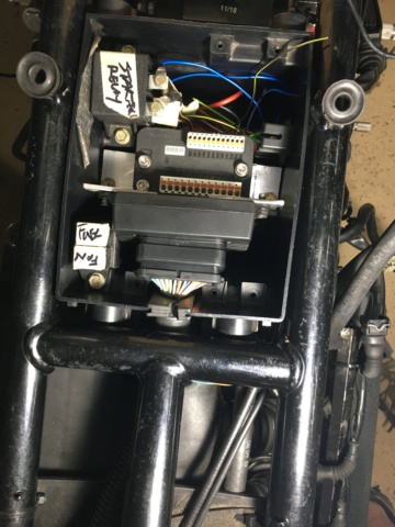
So I had to crack open the Microsquirt case and trace out where the path to ground was broken. On visual inspection I didn't see any burn marks or indication of fried electronics on the printed board, but this thing is so extremely tiny in the circuity, to be honest it could have fried anywhere along and I wouldn't have noticed. I checked for continuity all the way up to a resistor in the board, and wouldn't you know it, on the side that continues into the Microsquirt I got the continuity "beep" but from the resistor out to the pin which eventually leads to the igniter, I got nothing.
So at this point, one would assume that this TINY ASS resistor was fried. I surgically jumpered around it with a 100ohm resistor and reassembled.
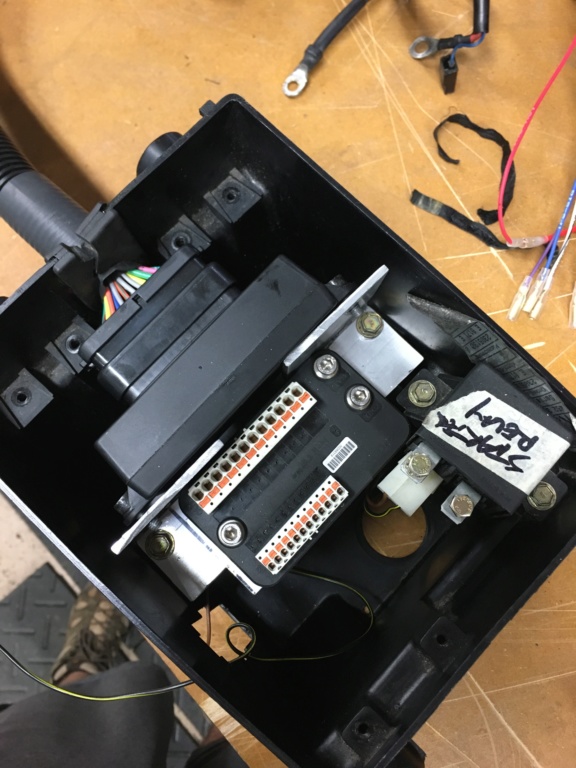
In the spirit of reducing wiring, and making things as compact/efficient as possible. To replace the igniter I found one of these:

This is a Bosch wasted spark "smart" coil pack. It combines both an igniter and the coils in one package. This type of smart coil is also spec'ed out in the Microsquirt installation documents as a suitable option. The cost was pretty much the same as sourcing the original igniter. I went with the smart coil combo.
With the Microsquirt reassembled and the new smart coil pack installed, I ran through the testing using the test option in TunerStudio and all was working again!
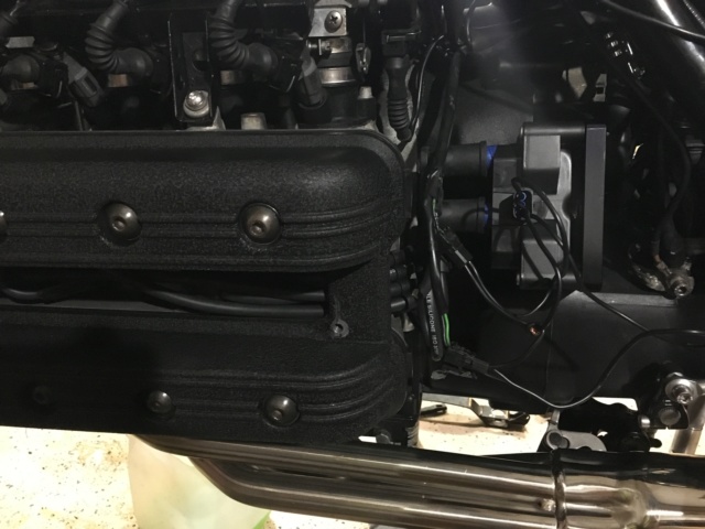
For the time being, I DIY'ed a mounting plate for the coils:

I'm not quite satisfied with how the plate ended up, I actually just received in the mail the other day a coil pack bracket from a K1200 for a more solid mounting point. I may need to modify it just a bit, but that's a project for later.
Now back to the starter kickback... timing timing timing. Also, proper injector bank wiring. These contributed to the kickback issue I was facing.
Here's how I got things worked out:
In TunerStudio, Instead of using a not yet tuned ignition timing map while you're setting things up, you can lock the timing in the software just for this purpose of testing and adjusting the timing.
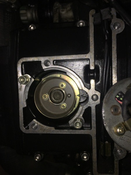
I have the hall effect sensor plate as perfectly aligned with the edges of the curves as possible. I wanted to have as clear of a window view of the notch and case marker as I could. Since it's set and that I can control the trigger angle in TunerStudio, I should never have to move the HES plate manually to adjust timing later on.

I removed the spark plugs, locked the timing in the software to 0°, began firing the timing light while cranking. There is a feature called "Trigger Wizard" that you can adjust the trigger angle on the fly as you are cranking until it matches up with the engine's timing marks. My goal here was to get the triangle notch to align with the TDC marker on the engine case so that I could be sure at what degree TunerStudio was reading as top dead center.
The result of this was that my timing marks line up at 45° as TDC. Knowing that K1100 spec for setting timing is 6° BTDC, its simple to get the final timing adjustment degree setting. 45° TDC - 6° spec'ed BTDC =
38° BTDC final trigger angle.OK, I got my trigger angle set. If I see that after this process that it's off when the engine is idling with a timing light, I can make fine adjustments to the final trigger angle in the software to really dial it in. But for now, a degree or so off is fine. Confident that the ignition timing was now set, It was back to getting the K started and idling.
The K would start (meh sometimes), but idled like complete garbage. There were sometimes where it wouldn't even start. But hey, NO STARTER KICK BACK!!! Well, this is where proper injector bank wiring comes into play.
There are two injector bank control wires coming from the Microsquirt (labeled as "INJ1" and "INJ2"). You can run up to 4 injectors per bank wire for an 8 cylinder engine. I do have it wired into split banks. Initially I had INJ1 connected to injector pair 1 and 4, and INJ2 connected to pair 2 and 3. My initial thinking was that I should wiring them similar to how the coils are connected to the coil pack. WRONG.
Reading through some of my past notes, I found that the proper firing order is 1-3-4-2. Reworking the wiring, the injector pairing is now:
INJ1 – Injector 1 + Injector 3
INJ2 – Injector 2 + Injector 4
After these changes the bike fired right up and idle. All be it, I needed to open the choke and make adjustments to the idle screws initially. The fuel table will need to be tuned. At this point, the project is up to date.
Now, on to the ignition timing table in TunerStudio. I've done some deep web research into unraveling the mystery of ignition timing of the BMW K1100 in order to generate a viable ignition table to start with and test.
If anyone has any comments or more insight into this area, please feel free to correct me to add to the project. Here is the table that I have come up with:

Key takeaways from my research to get to the table map above. Timing is set at 6° up until 1300 RPM after that, timing increases as RPMs rise up to 6,000 RPM where "full on advance" is set at 30° and above. The column at 8777 is what I read to be the overrun safety in order to protect the engine from damage. Timing is set back to 6° at 8777 RPM.
With the important points established in the table map (6° at idle up to 1300 RPM, 30° full advance at 6,000 RPM, timing reset to 6° at 8777), there is an interpolate feature that will automagically generate the values between the columns. That is how I came to the values between columns 1300 RPM and 6,000 RPM.
I will note that this is most definitely an UNTESTED and UNOFFICIAL ignition table.
I'm aware to have any verification about power and efficiency the bike will need to be dyno'ed. One day I will do that. But for right now, I am going by feel to see what the engine wants.
Again, I'm open to anyone who has knowledge on this subject. I will post further on the results of the initial ignition table and once the fuel table are dialed in.
I'm feeling I might actually get her on the road in the coming weeks!!!


 93 K1100LT Microsquirt Sat Nov 30, 2019 3:42 pm


