1

 Fuel light unit Sat Sep 11, 2010 5:45 am
Crazy Frog
admin

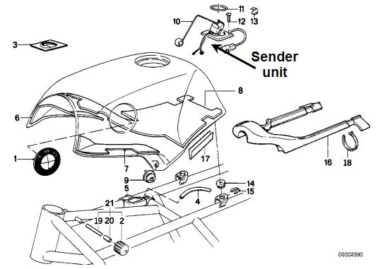
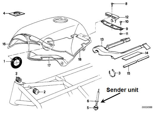
My 1985rt is equipped with a mechanical fuel sender unit to control the 7L and 4L fuel lights.


Other models are equipped with an electronic sender unit.


Here is the inside of the fuel sender:

I was under the impression that the electronic unit was only for the bikes equipped with a fuel gauge. On the schematic, I cannot see any connection for a gauge. I see only the 7L and 4L dash lights and reading about it, I found the following description. Do I miss something or another type of sender is used for the gauge?
There are two thermistors housed in the fuel sender unit which is located in the fuel tank. The thermistors are positioned at two different levels corresponding to 7 and 4 litres. When the thermistor is exposed to the air in the tank the appropriate light is illuminated.
Each thermistor is supplied with 12 volts that is current limited to 95mA, this current limit is controlled by the BD240A's and there accompanying circuitry. With the applied voltage the thermistors self heat, when they are immersed in fuel the heat is dissipated and the resistance is approximately 600 ohms. While the thermistor is immersed in fuel the inverting input of the op-amp has 12 volts applied to it. This voltage level is above the 4.7 volt reference applied to the non-inverting input of the op-amp and thus the output of the op-amp is below the 0.7 volts needed to turn on the NPN transistor (BD877) which controls the lamp. When the thermistor is above the fuel level and in air, the self heating causes its resistance to drop below 53 ohms, the voltage at the inverting input of the op-amp drops with it to below the 4.7 volt reference level applied to the non-inverting input of the op-amp. This causes the output of the op-amp to swing to its maximum positive level (+12V).


Other models are equipped with an electronic sender unit.


Here is the inside of the fuel sender:

I was under the impression that the electronic unit was only for the bikes equipped with a fuel gauge. On the schematic, I cannot see any connection for a gauge. I see only the 7L and 4L dash lights and reading about it, I found the following description. Do I miss something or another type of sender is used for the gauge?
There are two thermistors housed in the fuel sender unit which is located in the fuel tank. The thermistors are positioned at two different levels corresponding to 7 and 4 litres. When the thermistor is exposed to the air in the tank the appropriate light is illuminated.
Each thermistor is supplied with 12 volts that is current limited to 95mA, this current limit is controlled by the BD240A's and there accompanying circuitry. With the applied voltage the thermistors self heat, when they are immersed in fuel the heat is dissipated and the resistance is approximately 600 ohms. While the thermistor is immersed in fuel the inverting input of the op-amp has 12 volts applied to it. This voltage level is above the 4.7 volt reference applied to the non-inverting input of the op-amp and thus the output of the op-amp is below the 0.7 volts needed to turn on the NPN transistor (BD877) which controls the lamp. When the thermistor is above the fuel level and in air, the self heating causes its resistance to drop below 53 ohms, the voltage at the inverting input of the op-amp drops with it to below the 4.7 volt reference level applied to the non-inverting input of the op-amp. This causes the output of the op-amp to swing to its maximum positive level (+12V).

Last edited by Crazy Frog on Sun Feb 13, 2011 6:36 pm; edited 2 times in total
__________________________________________________
  1986 k75, 1985 K100rt, 1986 k75, 1985 K100rt, |


