BMW K bikes (Bricks)


You are not connected. Please login or register

View previous topic View next topic Go down  Message [Page 1 of 1]


1Back to top Go down   hall sensor wiring Empty hall sensor wiring Sat Feb 24, 2018 10:38 am

mister_anger

mister_anger
Silver member
Silver member
hello,

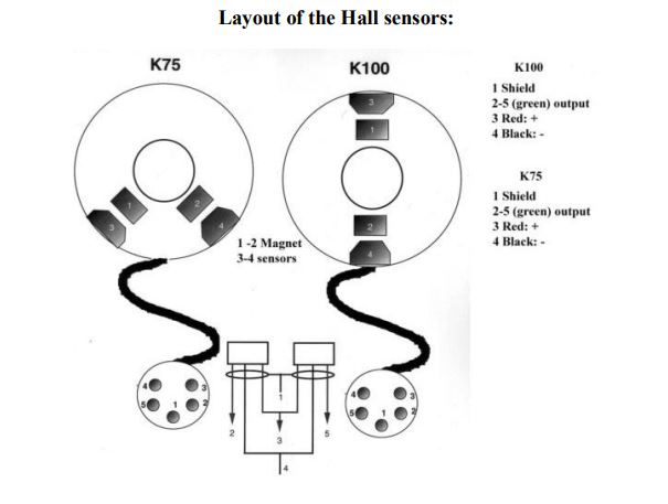
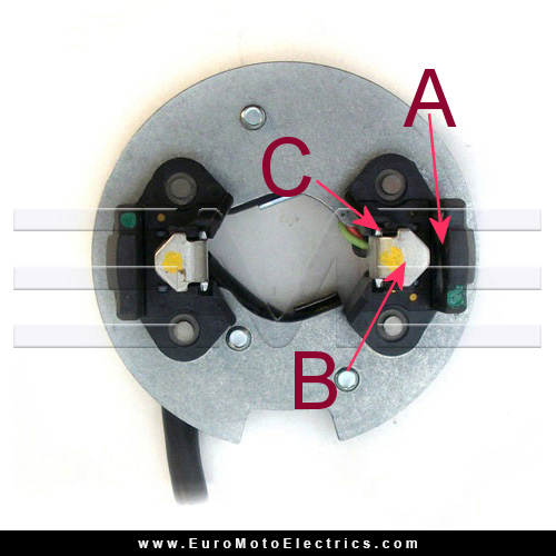
My K100 will not start and I am working trough CF troubleshooter. Tested the hall sensors today and the test failed. Now the question is if it is the sensors that are broken or the wiring from the plug to the sensors. Does anybody know how to measure the continuity between the plug and the sensors without having to take of the sensors and discontect the wiring. In the troubleshooter it is not really clear to me wich wire goes to wich point of the sensors.
thanks, M


2Back to top Go down   hall sensor wiring Empty Re: hall sensor wiring Sat Feb 24, 2018 10:54 am

mister_anger

mister_anger
Silver member
Silver member
hall sensor wiring Hall_s10
hall sensor wiring Boigns10

So the question is if the black, red and green wire is connected with A, B or C.
If I know this then I can measure the continuity from the plug to point A,B or C.


3Back to top Go down   hall sensor wiring Empty Re: hall sensor wiring Sat Feb 24, 2018 12:23 pm

Inge K.

Inge K.
VIP
VIP
Hope this helps.

hall sensor wiring Chyme10

It's Chinese copy (Chyme 56).....from www.hallsensors.de.
It doesn't match with the drawing in your post (with 12V- in the middle,
just as in BMW's own diagrams...which I'll guess is the basis for the drawing).
But on the other hand the drawing doesn't make sense either, as it must
be two different sensors as one is a mirror image of the other.
Unless I misunderstand something (happens all the time).
But it does match with the colour order on the sensors used by Bosch
which can be seen on the EME page where your pic originates.

It could be that the colour order have been changed during the years
(but I doubt it).
The sensors which was used back then was made by Honeywell,
which is NLA these days.
Difficult to know which sensors Bosch using these days.

Here is the datasheet from Honeywell, which using the same colour order.


Last edited by Inge K. on Sat Feb 24, 2018 6:23 pm; edited 1 time in total (Reason for editing : Don't remember....at this time on a saturday.)


__________________________________________________
Inge K.
K100RS -86. (first owner), K1100LTSE -94.
    

4Back to top Go down   hall sensor wiring Empty Re: hall sensor wiring Sat Feb 24, 2018 2:38 pm

Point-Seven-five

Point-Seven-five
Life time member
Life time member
If you want to check continuity you will have to remove the plate from the engine so you can get to the wires on the back.  Then you can use a needle to pierce the insulation to check continuity.  Use the thinnest needle you can find to minimize the damage to the insulation.

As long as each wire at the plate has continuity to a pin on the connector I wouldn't worry about which color goes where. 

What is more important is to do a functional test of the sensors by applying power to them and observing whether they change output state when a piece of steel is moved through the gap.


__________________________________________________
Present: 1991 K100RS "Moby Brick Too"
 
Past:
1994 K75RT "Ilsa, She Wolf of the SS"
1988 K100RS SE "Special Ed"
1994 K75S "Cheetos"
1992 K100RS "Moby Brick" R.I.P.
1982 Honda FT500
1979 Honda XR185
1977 Honda XL125
1974 Honda XL125
1972 OSSA Pioneer 250
1968 Kawasaki 175
    

Sponsored content


View previous topic View next topic Back to top  Message [Page 1 of 1]

Permissions in this forum:
You cannot reply to topics in this forum