BMW K bikes (Bricks)


You are not connected. Please login or register

View previous topic View next topic Go down  Message [Page 1 of 1]


1Back to top Go down   K75 Scrambler + Acewell speedo Empty K75 Scrambler + Acewell speedo Mon Jul 03, 2017 2:15 pm

NaelRiou

NaelRiou
active member
active member
Hi guys,

I have a 1991 K75 and I customized it on a kind of Scrambler. My project is almost done and I took the time to do it because I didn't want to my mechanical engineering diploma. I tried to build has much as I can, and I like to find the inspiration by looking at a bunch of pieces in my workshop. The tricky part is for the speedo, like many people, I bought an Acewell and like many people, I'am struggling with the wires so I'll try and just let you know how it goes !

Cheers !


K75 Scrambler + Acewell speedo 19748010

[url=https://servimg.com/view/19728162/4]K75 Scrambler + Acewell speedo 19264010[/url]
K75 Scrambler + Acewell speedo 19532710

K75 Scrambler + Acewell speedo 19650510


2Back to top Go down   K75 Scrambler + Acewell speedo Empty Re: K75 Scrambler + Acewell speedo Mon Jul 03, 2017 2:28 pm

NaelRiou

NaelRiou
active member
active member
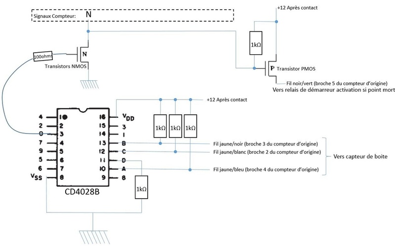
Ok so I gathered a lot of info about the Acewell 2853 and how I can plug it, problems etc...

For the Neutral problem : In fact if you just plug, it doesn'it work well, I found this solution :


K75 Scrambler + Acewell speedo Captur10


Because my Acewell doesn't have the gear engaged I just need the Neutral position


3Back to top Go down   K75 Scrambler + Acewell speedo Empty Re: K75 Scrambler + Acewell speedo Mon Jul 03, 2017 2:46 pm

NaelRiou

NaelRiou
active member
active member
The best way to install an Acewell speedo on a K bike is to buy the BEP 2.0 or 3.0 from Maru Labs which allows you to simply plug and play your old speedo with a new one, very simple, very clever, but very expensive to, more than 130€ for the BEP 2.0. Too expensive for me so I decided to inspiring myself from Maru labs because it is an open source system so you can build your own one.

Here is something useful :

electronic diagram of the BEP 2.0 :http://maru-labs.com/wp-content/uploads/2015/10/BEB2.0_Schema.pdf

documentation on the BEP 2.0 :http://maru-labs.com/wp-content/uploads/2016/03/BEP2_Anleitung_V4.pdf

It's in german but I have nothing better, if you have please share ! Very Happy

The idea is not to reproduce the same adapter but just to use some parts of the diagram to solve problems encountered with the Acewell. For example, I want to use the original Hall effect sensor but I know that the adapter is useless for the tachymeter and that I have to use the one given with the Acewell


4Back to top Go down   K75 Scrambler + Acewell speedo Empty Re: K75 Scrambler + Acewell speedo Mon Jul 03, 2017 5:03 pm

robmack

robmack
Life time member
Life time member
http://www.motobrick.com/index.php/topic,3421.0.html

I can build just the speedometer conditioning circuit if you need that functionality.

The tach is easy. Either wrap 6-7 turns of 22AWG stranded wire around the spark lead for Cylinder #1 and attach the other end to the RPM input on the Acewell. Or connect the RPM input of the Acewell to the Black/Blue wire (Pin 16). This may require a conditioning circuit to prevent the RPM needle from jumping around at low RPMs.


__________________________________________________
Robert
1987 K75 @k75retro.blogspot.ca
http://k75retro.blogspot.ca/
    

5Back to top Go down   K75 Scrambler + Acewell speedo Empty Re: K75 Scrambler + Acewell speedo Sun Jul 09, 2017 2:29 pm

NaelRiou

NaelRiou
active member
active member
Sorry, I was very busy this week ! Thanks Robmack, it's very helpful ! The Neutral circuit is perfect. In fact I would like to improve my skills and understand how it works, so I'll try to build the neutral circuit and the speedo circuit, thank you for the diagram.

I'll do what you said for tach, it's not very dificult.

I have a question for the neutral circuit, which wire goes to my Acewell ? Because I think Pin2 = C ; Pin3 = B ; Pin4 = A ; Pin2 = A ; Pin6 = Start enable and the Neutral goes to the Acewell right ?

Also, If you have the diagram for the speedo circuit, it would be so great ! Very nice job

Thanks for all Robmack ! Can't wait to drive the K bounce


6Back to top Go down   K75 Scrambler + Acewell speedo Empty Re: K75 Scrambler + Acewell speedo Sun Jul 09, 2017 2:41 pm

robmack

robmack
Life time member
Life time member
Hi,

The pin assignment you outlined is incorrect.
A = Pin 4 (Yellow/Blue)
B = Pin 3 (Yellow/Black)
C = Pin 2 (Yellow/White)
Start Enable = Pin 5 (Black/Green)
Yes the neutral output goes to the Acewell.

This is the schematic diagram for the speedo conditioning circuit. https://goo.gl/photos/3Qsht7C5YSzt9Ak4A


__________________________________________________
Robert
1987 K75 @k75retro.blogspot.ca
http://k75retro.blogspot.ca/
    

7Back to top Go down   K75 Scrambler + Acewell speedo Empty Re: K75 Scrambler + Acewell speedo Sun Jul 09, 2017 4:44 pm

NaelRiou

NaelRiou
active member
active member
Wow ! big thank you robmack, you are fantastic ! I'll build it and let you know how it goes cheers


8Back to top Go down   K75 Scrambler + Acewell speedo Empty Re: K75 Scrambler + Acewell speedo Tue Jul 11, 2017 9:45 am

NaelRiou

NaelRiou
active member
active member
Ok for the neutral circuit with the four relays, I think I should buy :

1 diode 1kV, 1A, 2.5V, 30A : HERE


4 relays SPDT 12VDC, 1A : HERE
 
For K2, K3, K4 : 3 transistors MOFSET, Canal N, 16A, 60V, 0.07ohm, 10 V, 1V : HERE

For K1 : 1 transistors MOFSET, Canal P, -8.8A, -60V, 0.23ohm, -10 V, -3V :HERE

Or, instead of this kind of transistors above, could I use SMBAT42 like the speedo circuit ?

What do you think about that ?  Smile


9Back to top Go down   K75 Scrambler + Acewell speedo Empty Re: K75 Scrambler + Acewell speedo Tue Jul 11, 2017 11:29 am

robmack

robmack
Life time member
Life time member
Hi NaelRiou,

I'm not sure I understand where you are referencing the transistors K1 - K4. The neutral detect circuit has no transistors in its construction and the speedo conditioning circuit uses an Op-amp, a small signal transistor and some passive components. Those N-channel and P-channel FETs you linked are quite large. Can you help me understand where you are going to use these devices?

As for the relays and diode you've selected, they will work just fine.


__________________________________________________
Robert
1987 K75 @k75retro.blogspot.ca
http://k75retro.blogspot.ca/
    

10Back to top Go down   K75 Scrambler + Acewell speedo Empty Re: K75 Scrambler + Acewell speedo Thu Jul 13, 2017 7:57 am

NaelRiou

NaelRiou
active member
active member
Ok thank you ! In fact, I'm trying to find the good componants for each circuit. The speedo circuit is ok for me, I identified the differents componants. I've just some trouble with the neutral circuit to identified the componants in it.

I think in the red circle is the relay and I thought the yellow circle was a transistor but you told me it's not, so I don't know which componant it is scratch

K75 Scrambler + Acewell speedo Neutra10


11Back to top Go down   K75 Scrambler + Acewell speedo Empty Re: K75 Scrambler + Acewell speedo Thu Jul 13, 2017 8:42 am

robmack

robmack
Life time member
Life time member
Oh, ok.  Now I get it.  K1 -K4 are 4 relays.  Here is the schematic:

K75 Scrambler + Acewell speedo Pb-AP5NQyImORgzAJDvmEtRI1dqoWYFvo-U_5xgR-DRUYPneaYkOTMpSU7ffj5lo2NWWs9EHIqy2QneX-yQPsNS8VTC-QltaAU8GCID_vDC38V6DcqbRhEmWKAD0xnRjSHB82WCebyrJ58lZuwh4YFvlF5OBVQY0EDK067qNU9sBxvpgiYvLWn3qeS-lz_icI8goVxpOXPbo4L7FbL_EU4fjTLtYnSBcFuc0BnCIiTpHrIDEe4RbNC38YNJ1nSt4skXOyxJf7HzFj6UijS0TFbVBECmawmdtfZadqW13FURMPMkFkCUXkHaGCU2UGZqMnuCF6TGefbMV--JA-i7L_4-FTv5gxI56IcbPTRlfQQtyTzc_iBAqG3LpnUifhXFqYJqZvvDqdbGf8s_60x3RdUvviFIcVGOHIg83YmHrGQLblGTZr5yjmnDZbawXYiEmvmNrgjKyAzdxw9R44pUMLyMI5xYTuGxSwwvg5FJSEv1G-po-IqJMXQMhPQUOsjiJHymXgIEkpuZuRJjlAotHDmwuGINL_hBpyyK2J9yBYv-ZqiZagoJAis5Hg0-B-6sDFw6Bp-WG8miPl8-Y2iD1QWG0JN15v6m3_dL9AG-W_7F8tG41k5Nh_CSuLiuoUr-kFfi3vV4myb6z-MYLqMOih2fpA5OSDzRxPnP8H5zqFiMzjg=w898-h844-no

The PCB is derived from this schematic. The red circled and yellow circled pads are the 5 pins for a complete relay - 2 for coil, one for common, one for NO and one for NC. You can actually see the connection outline on the top silkscreen, with the contact arrangement, coil and relay outline.

I've sent that design off for manufacture and it is on its way through the mail to me.  The relays I selected in that design are SONG CHUAN 833H-1C-C.


__________________________________________________
Robert
1987 K75 @k75retro.blogspot.ca
http://k75retro.blogspot.ca/
    

12Back to top Go down   K75 Scrambler + Acewell speedo Empty Re: K75 Scrambler + Acewell speedo Fri Jul 14, 2017 2:41 pm

NaelRiou

NaelRiou
active member
active member
Okaaayy ! I understand ! As you can see, I need to learn more ! I bought the componants, they will arrive next week. I hope to build the circuits next Sunday.

Thanks ! Very Happy


13Back to top Go down   K75 Scrambler + Acewell speedo Empty Re: K75 Scrambler + Acewell speedo Sun Jul 23, 2017 9:40 am

NaelRiou

NaelRiou
active member
active member
Ok so I received all the componants for the PCB and I redesign the neutral circuit because my relays are different from the SONG CHUAN relays. I'll build the circuit tomorow.

But before that, I installed the Acewell and connect the wire without the PCB, just to see what happens.
I connected the wires with diagrams and here are the problems :

- When I push on the start button, nothing happen so the moto does not start (why ?)
- Right turn works fine but the left one causes a very weird noise in the fuse case under the tank
- High Beam does work well only when I flash

Plus, I noticed that if I don't connect blinkers, the horn doesn't work besaute it is part of the closed circuit with the blinkers.


14Back to top Go down   K75 Scrambler + Acewell speedo Empty Re: K75 Scrambler + Acewell speedo Sun Jul 23, 2017 10:56 am

robmack

robmack
Life time member
Life time member
- When I push on the start button, nothing happen so the moto does not start (why ?)
Because you haven't finished building and installing your neutral detect circuit.  Have you tried pushing the start button while pulling in the clutch?

- Right turn works fine but the left one causes a very weird noise in the fuse case under the tank
From your pictured in the first post in this thread, it looks like you have aftermarket lighting.  Are the signal lamps actually LEDs??  If so, that will account for the weird operation of the signals.  The flasher relay is not compatible with LEDs as it stands.  You have to modify it slightly to make it work properly.

- High Beam does work well only when I flash
This is because there is something going on with your righthand switch cluster.  I see that you have a Euro style cluster with a headlight switch.  There is a problem with that switch or the connector or the continuity over the White/Yellow wire from that switch to the Hi-Lo switch in the lefthand cluster.  Trace the that wire to find out what's going wrong.


__________________________________________________
Robert
1987 K75 @k75retro.blogspot.ca
http://k75retro.blogspot.ca/
    

15Back to top Go down   K75 Scrambler + Acewell speedo Empty Re: K75 Scrambler + Acewell speedo Sun Jul 23, 2017 11:59 am

NaelRiou

NaelRiou
active member
active member
Ok great to know that !

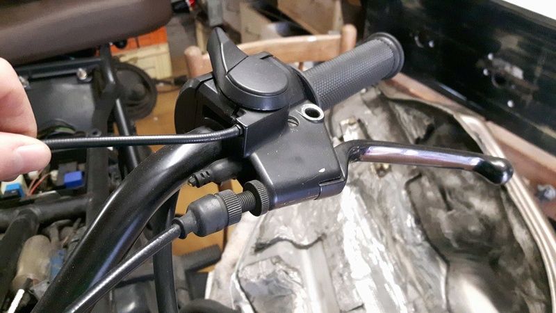
- The bike doesn't start while pulling the clutch, in fact, I think the previous owner cut the wire of the clutch detector, so the moto doesn't detect the pulling clutch and the engine stay silent.

K75 Scrambler + Acewell speedo 20394510

-Blinkers are not LED, but with classic bulb, when I had the original speedo, everything worked fine, it's at this moment that I decided to change the speedo. So the blinkers were working well, they were flashing a bit faster than the original (too much if I'm honest), but they were working well.

- Ok I will investigate for the high beam problem !

Thanks Robmack ! I let you know how it goes !


16Back to top Go down   K75 Scrambler + Acewell speedo Empty Re: K75 Scrambler + Acewell speedo Sun Jul 23, 2017 5:38 pm

NaelRiou

NaelRiou
active member
active member
So here my connection for the moment :

Acewell / Original Plug :

Ground (Black) / Pin 13 Ground (Brown)
Clock power (brown) / Pin 1 clock power (red and white)
Speed (white) / From the PCB
switch key (red) / Pin 6 +15V (black and green)
Fuel tank / bypassed by the 100ohm resistor included in the acewell circuit for the moment
RPM / From a little conditionning circuit with a capacitor and a a resistor

Right turn indicator (green) / Pin 17 Right turn indicator (blue and black)
oil temperature (orange) / Pin 11 Oil light (Brown/Green)
Neutral (grey) / from the PCB
Warning (purple) / Pin 8 ABS/Warning relay (green and yellow)
High beam light (yellow) / Pin 15 high beam (white)
left turn indicator (brown) / Pin 19 left turn indicator (brown)

K75 Scrambler + Acewell speedo 20353810

I read in one of your post that it was important to add a LED to enable the alternator.

Maybe my blinkers problem is caused by the not connected pin 24 and 18 ?

I saw your blog, very impressive !


17Back to top Go down   K75 Scrambler + Acewell speedo Empty Re: K75 Scrambler + Acewell speedo Sun Jul 23, 2017 6:02 pm

robmack

robmack
Life time member
Life time member
Hope this is a typo error on your part:

left turn indicator (brown) / Pin 19 left turn indicator (brown)

Should be and you actually didn't connect a Brown wire.
left turn indicator (brown) / Pin 19 left turn indicator (Blue and Red)

Maybe another typo:
switch key (red) / Pin 6 +15V (black and green)

Should be:
switch key (red) / Pin 6 +15V (Green and black)

Other than those small items, the wiring looks correct.  The fact that Ground on Pin 18 is not connected is not an issue.  Brown on Pin 23 needs to be connected to your PCB; I hope it is.  Pin 24 is switched power but you already have switched power from Pin 6, so not an issue either.

If the flashers were working with the OEM gauge cluster attached but they seemed a "bit fast", then that sure tells me that the bulbs are most probably LEDs. Read this thread: http://www.motobrick.com/index.php?topic=659.0


Last edited by robmack on Sun Jul 23, 2017 6:13 pm; edited 1 time in total


__________________________________________________
Robert
1987 K75 @k75retro.blogspot.ca
http://k75retro.blogspot.ca/
    

18Back to top Go down   K75 Scrambler + Acewell speedo Empty Re: K75 Scrambler + Acewell speedo Sun Jul 23, 2017 6:12 pm

NaelRiou

NaelRiou
active member
active member
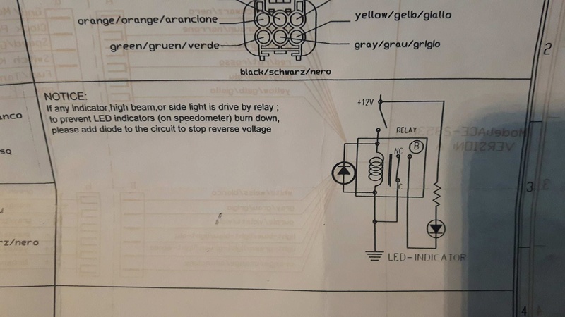
K75 Scrambler + Acewell speedo 20348110

Am i consered about that ?


19Back to top Go down   K75 Scrambler + Acewell speedo Empty Re: K75 Scrambler + Acewell speedo Sun Jul 23, 2017 6:15 pm

robmack

robmack
Life time member
Life time member
The flasher "relay" is not really a relay as used in that context refered to in your picture from the manual.  The K75 flasher "module" (as it may more aptly be called) is a complex electronic circuit, and not a simple relay as may be found on Japanese motorcycles.  You need to read that page I linked to.


__________________________________________________
Robert
1987 K75 @k75retro.blogspot.ca
http://k75retro.blogspot.ca/
    

20Back to top Go down   K75 Scrambler + Acewell speedo Empty Re: K75 Scrambler + Acewell speedo Sun Jul 23, 2017 6:18 pm

NaelRiou

NaelRiou
active member
active member
Yes sorry, my fault, it's a bit late in france Razz 

I agree with your corrections


21Back to top Go down   K75 Scrambler + Acewell speedo Empty Re: K75 Scrambler + Acewell speedo Sun Jul 23, 2017 6:39 pm

NaelRiou

NaelRiou
active member
active member
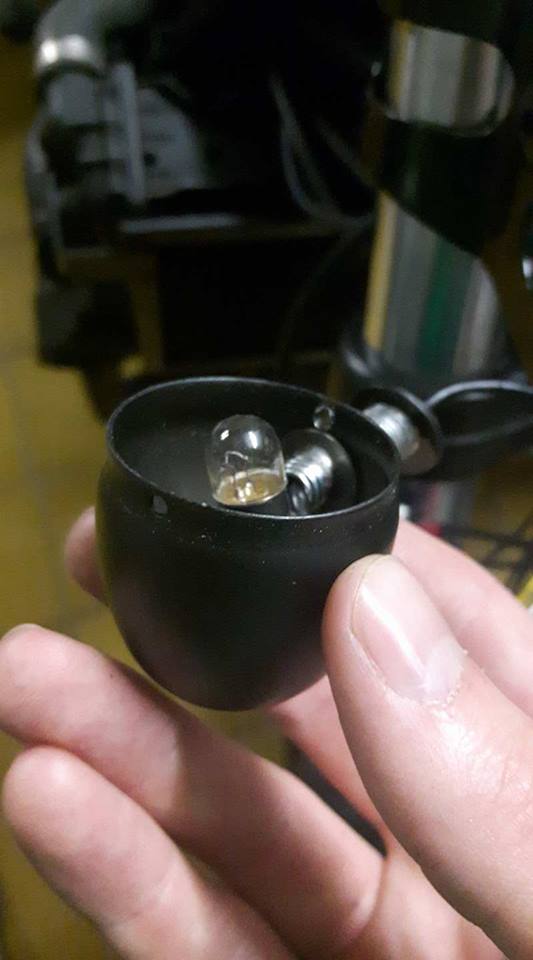
here the pictures of the turn signals, it's not LED is it ?

K75 Scrambler + Acewell speedo 20370910
K75 Scrambler + Acewell speedo 20289710


22Back to top Go down   K75 Scrambler + Acewell speedo Empty Re: K75 Scrambler + Acewell speedo Sun Jul 23, 2017 7:19 pm

NaelRiou

NaelRiou
active member
active member
Okay, I read that if the bulb has not the same power to the previous one, the flash could be slower or faster. If it's faster, adding a resistor in parallel could solve the problem. I'll check that after having installed the Acewell properly ! Smile


23Back to top Go down   K75 Scrambler + Acewell speedo Empty Re: K75 Scrambler + Acewell speedo Sun Jul 23, 2017 8:15 pm

NaelRiou

NaelRiou
active member
active member
Here are details of the circuit I will build :

The neutral circuit : in red, the four relays and in green the diode


K75 Scrambler + Acewell speedo Explic10

The speedo circuit : in green, it is the capacitor


K75 Scrambler + Acewell speedo Explic12

The tachometer circuit :

K75 Scrambler + Acewell speedo Explic11


I did it on Catia because I have zero knowledges in electronic, I tried some softwares, but it was faster for me on catia lol!


24Back to top Go down   K75 Scrambler + Acewell speedo Empty Re: K75 Scrambler + Acewell speedo Sun Jul 23, 2017 10:28 pm

robmack

robmack
Life time member
Life time member
All the circuits look correct.

One change I would suggest is to connect up the unused OP-AMP in the LM358; don't leave the pins floating because it will cause oscillations and excess current draw.  The best plan is to connect the output of the op-amp to its inverting input, and the non-inverting input to the base of the SMB42A.  Refer to Figure 3(a) in this web page: http://www.electronicproducts.com/Analog_Mixed_Signal_ICs/Amplifiers/Properly_terminating_an_unused_op_amp.aspx


__________________________________________________
Robert
1987 K75 @k75retro.blogspot.ca
http://k75retro.blogspot.ca/
    

25Back to top Go down   K75 Scrambler + Acewell speedo Empty Re: K75 Scrambler + Acewell speedo Mon Jul 24, 2017 9:08 am

NaelRiou

NaelRiou
active member
active member
You mean like this ?

K75 Scrambler + Acewell speedo Explic14


26Back to top Go down   K75 Scrambler + Acewell speedo Empty Re: K75 Scrambler + Acewell speedo Mon Jul 24, 2017 7:40 pm

robmack

robmack
Life time member
Life time member
Yes.


__________________________________________________
Robert
1987 K75 @k75retro.blogspot.ca
http://k75retro.blogspot.ca/
    

27Back to top Go down   K75 Scrambler + Acewell speedo Empty Re: K75 Scrambler + Acewell speedo Sun Jul 30, 2017 11:30 am

NaelRiou

NaelRiou
active member
active member
Okay, so I build the neutral circuit, I connected it and... nothing. I was very disapointed. Then, I watch very carefully my diagram, and I realized that there was a mistake. One of the wire wasn't soldered on the good pin of a relay. I made the change, connected the circuit and...

IT WORKS PERFECTLY !!!! The moto starts !

Here is the new circuit ! and the mistake corrected in the red circle so now it works perfectly :

K75 Scrambler + Acewell speedo Explic15

Thanks a lot !

Today, I'll make the tacho PCB and I'll try to figured out why do the blinkers doesn't work properly. Maybe It's because there is no more button for the warning, I think It could be an explanation.
So first of all and in order to don't create new problems, I'll installed all the bulbs, all the button and I'll see what happens. Then I could try something else.

For the blinkers, I had an idea, because the fast flash comes from the difference of power between the old and the new bulbs (old 21W / New 5W) so the idea is to consume more power. A resistance could be an idea but it'is a bit difficult to find the appropriate one, so an idea could be to hide bulbs on the circuit to consume more power. Just an idea, I'll study that option later.


28Back to top Go down   K75 Scrambler + Acewell speedo Empty Re: K75 Scrambler + Acewell speedo Sun Jul 30, 2017 11:59 am

robmack

robmack
Life time member
Life time member
Congratulations on the neutral detect circuit working.

If the bulbs are lower wattage than BMW specified, the flasher module will hyperflash (blink the bulbs at a higher rate than normal)  LEDs cause the same effect as low wattage bulbs.  Adding a parallel resistor across each bulb will solve the problem but a better, easier solution is to cut the PCB trace as detailed in that link I pointed you to in Post #17 above.  Parallel resistors will consume power and only create heat which is a waste. You'll have to size the resistors properly as well as find a way to heat-sink them to the frame so they don't overheat.


__________________________________________________
Robert
1987 K75 @k75retro.blogspot.ca
http://k75retro.blogspot.ca/
    

29Back to top Go down   K75 Scrambler + Acewell speedo Empty Re: K75 Scrambler + Acewell speedo Tue Nov 28, 2017 6:11 pm

NaelRiou

NaelRiou
active member
active member
Hi ! I'm back !

I finished to solder every wire and it works perfectly !

For the blinker I just had to buy new bulb with the good spec. --> 12V 22W something like that so now they flash at a normal speed.

For the tachymeter, I rolled a wire aroud the wire of the 1st ignition coil and I had to add a resistance of 1Mohm to get more steady signal so now it works perfectly.

It was'nt easy at all as no complete tutorial exists so I had to collect a lot and a lot of information, sometimes false but a lot, then think like an engineer and do the work. Now it works and I'll explain step by step, that way everybody with a bit of patience won't have to spend a fortune to buy the Marulab accesory and will be more clever than before


[url=https://servimg.com/view/19728162/21]K75 Scrambler + Acewell speedo 24197310[/url]
K75 Scrambler + Acewell speedo 24169710
[url=https://servimg.com/view/19728162/23]K75 Scrambler + Acewell speedo 24197110[/url]


30Back to top Go down   K75 Scrambler + Acewell speedo Empty Re: K75 Scrambler + Acewell speedo Tue Nov 28, 2017 9:45 pm

Dai

Dai
Life time member
Life time member
Good news! Very Happy


__________________________________________________
1983 K100 naked upgraded to K100LT spec after spending time as an RS and an RT
1987 K100RT
Others...
1978 Moto Guzzi 850-T3, 1979 Moto Guzzi 850-T3 California,1993 Moto Guzzi 1100ie California
2020 Royal Enfield Bullet 500
    

Sponsored content


View previous topic View next topic Back to top  Message [Page 1 of 1]

Permissions in this forum:
You cannot reply to topics in this forum