1

 How far into clutch driven friction plate should gearbox splines on K100 go? Thu Jan 21, 2016 1:13 pm
touchwoodsden
Silver member

Also posted on SucxkinDiesel forum
FrankenMoto BMW K 100/Smart CDI is coming along apace. (the original engine was clapped at early stage)
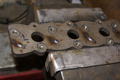
I really should try to slow down to avoid making cock-ups. Like this top one. Note welded cock up holes.
 DSC04234
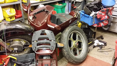
Not much room on floor so the bits are now in a shed next door.
 20151206_230412
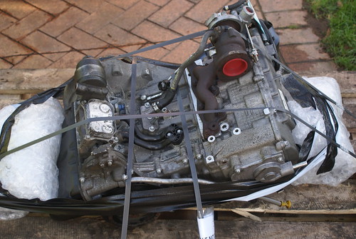
Look what arrived on Xmas eve.
 15
15
However mating the engine to the gearbox and lining it up has so far been very straightforward. I have a question at the end of this relating to the BMW clutch driven friction plate in relation to the gearbox input shaft.
One of these days I really will put all the photographs and words up that I have put together.
I hope to do it in some kind of order. Meanwhile, I have a couple of questions and a few photographs to “delight” or annoy anyone who doesnt like the idea of Diesel K100.
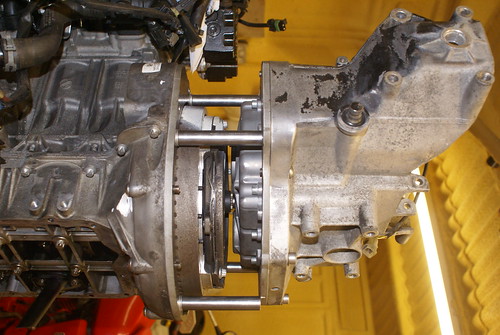
Here is the start of my Smart CDI/K 100 engine/gearbox adapter conversion. Lots of work to do but I’m really pleased with the way it’s all coming together.
 DSC04260
The question revolves around the relationship between the K 100 gearbox and the clutch driven plate.
 DSC04258
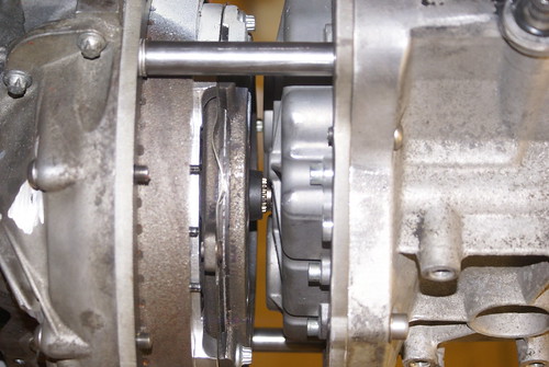
This is assembled with the clutch installed and you can see that there are a few splines poking out from the clutch driven plate centre?
 DSC04256
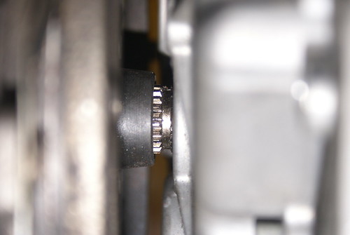
When I did my measuring and my calculations, (which may be flawed) it would have meant that there were no splines showing at all, but I put a couple of washers under each of the pillars and it has spaced it out a little more. The main reason behind that was the very small amount of clearance between the clutch outer metal driven plate and one of the shallow hex head socket bolts in the face of the gearbox which probably only had a millimetre or two of clearance. Enough?... but is it?
So, does anyone know exactly how far into the clutch the gearbox input shaft should be? Should it be all the way in so that there are just about no splines showing or is my 3 mm acceptable? I can soon get rid of the 3 mm by removing the washers from under the pillars.
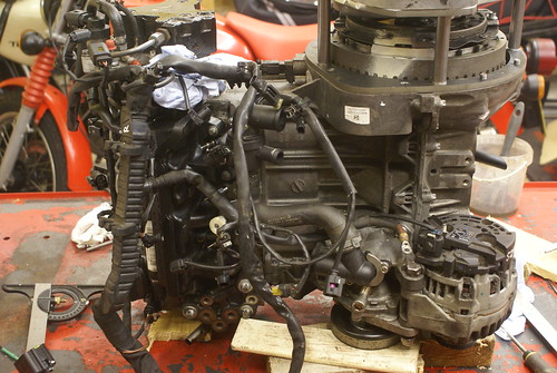
On a different note, I have loosely attached the engine loom (I was bored as it will be coming straight off while the engine is fitted) and there are lots and lots of connectors which obviously don’t do anything on the engine. Watch this space. Specialist Components here I come..on pay day.
 DSC04246
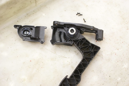
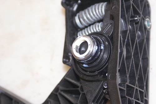
and finally, (Wrong thread really) the throttle pedal (plastic!) Is not what you would think, a wire wound potentiometer but it looks like a Hall Effect affair with a magnet inside. Therefore, I think I’m going to have to use the original assembly and get it to operate with a throttle to run the fly by wire throttle. Fortunately, inside the BMW fairing, that is lots of room to accommodate electronic wizardry. Suggestions welcome.
 DSC04239
 DSC04242
FrankenMoto BMW K 100/Smart CDI is coming along apace. (the original engine was clapped at early stage)
I really should try to slow down to avoid making cock-ups. Like this top one. Note welded cock up holes.
 DSC04234
 Not much room on floor so the bits are now in a shed next door.
 20151206_230412
 Look what arrived on Xmas eve.
 15
15 However mating the engine to the gearbox and lining it up has so far been very straightforward. I have a question at the end of this relating to the BMW clutch driven friction plate in relation to the gearbox input shaft.
One of these days I really will put all the photographs and words up that I have put together.
I hope to do it in some kind of order. Meanwhile, I have a couple of questions and a few photographs to “delight” or annoy anyone who doesnt like the idea of Diesel K100.
Here is the start of my Smart CDI/K 100 engine/gearbox adapter conversion. Lots of work to do but I’m really pleased with the way it’s all coming together.
 DSC04260
 The question revolves around the relationship between the K 100 gearbox and the clutch driven plate.
 DSC04258
This is assembled with the clutch installed and you can see that there are a few splines poking out from the clutch driven plate centre?
 DSC04256
 When I did my measuring and my calculations, (which may be flawed) it would have meant that there were no splines showing at all, but I put a couple of washers under each of the pillars and it has spaced it out a little more. The main reason behind that was the very small amount of clearance between the clutch outer metal driven plate and one of the shallow hex head socket bolts in the face of the gearbox which probably only had a millimetre or two of clearance. Enough?... but is it?
So, does anyone know exactly how far into the clutch the gearbox input shaft should be? Should it be all the way in so that there are just about no splines showing or is my 3 mm acceptable? I can soon get rid of the 3 mm by removing the washers from under the pillars.
On a different note, I have loosely attached the engine loom (I was bored as it will be coming straight off while the engine is fitted) and there are lots and lots of connectors which obviously don’t do anything on the engine. Watch this space. Specialist Components here I come..on pay day.
 DSC04246
 and finally, (Wrong thread really) the throttle pedal (plastic!) Is not what you would think, a wire wound potentiometer but it looks like a Hall Effect affair with a magnet inside. Therefore, I think I’m going to have to use the original assembly and get it to operate with a throttle to run the fly by wire throttle. Fortunately, inside the BMW fairing, that is lots of room to accommodate electronic wizardry. Suggestions welcome.
 DSC04239
  DSC04242


