BMW K bikes (Bricks)


You are not connected. Please login or register

View previous topic View next topic Go down  Message [Page 1 of 1]


1Back to top Go down   temperature gauge Empty temperature gauge Tue Aug 23, 2016 1:01 pm

brickrider2

brickrider2
Life time member
Life time member
I have a temperature gauge on my 1985 K100RS.  Lately the needle has on occasion become very nervous, swinging from side to side by about 40 degrees.  What am I to make of this?  Is the gauge failing?  Is it a sign of something more sinister?


2Back to top Go down   temperature gauge Empty Re: temperature gauge Tue Aug 23, 2016 1:12 pm

Born Again Eccentric

Born Again Eccentric
Life time member
Life time member
I had something similar to this on one of my LTs a while back - erratic reading, random swinging of the needle and then it went full scale (without associated fan cut in or engine cut out!). 

It turned out that one of the temperature meter wires was in the final stages of breaking (wire fatigue?) - can't remember which colour it was though. Meter went full scale when it eventually broke completely. Easy to fix and no problems since.


__________________________________________________
temperature gauge Uk-log10 temperature gauge Sco-lo15
                              Paul  temperature gauge 905546712

"Heidi" K100LT 1991 (Grey) (VIN 0190172 Engine No. 104EB 2590 2213) - 5th owner. January 2014 (34,000 - 82,818 miles and counting....)
"Gretel" K100LT 1989 (Silver Grey) (VIN 0177324 Engine No. 104EA 2789 2211) - 4th+ owner. September 2015 (82,684 miles and counting....). Cat C Insurance write-off rebuild Feb 17
"Donor" K100LT 1990 (Red)  (VIN 0178091 Engine gone to Dai) - 6th & final owner (crash write-off now donor bike).   June 2012 (73,000 miles) to November 2013 (89,500 miles)
    

3Back to top Go down   temperature gauge Empty Re: temperature gauge Tue Aug 23, 2016 1:49 pm

robmack

robmack
Life time member
Life time member
Most likely corrosion on the pins of the connectors that couple the gauge to the sensor. Clean and reseat the connectors several times to ensure good contact.


__________________________________________________
Robert
1987 K75 @k75retro.blogspot.ca
http://k75retro.blogspot.ca/
    

4Back to top Go down   temperature gauge Empty Re: temperature gauge Fri Sep 16, 2016 3:16 pm

broberg

broberg
active member
active member
Hi-jacking the thread a little,

Is there a digital temp gauge/display that will work with the existing temp sensor?


Last edited by broberg on Fri Sep 30, 2016 8:03 pm; edited 1 time in total


5Back to top Go down   temperature gauge Empty Re: temperature gauge Sat Sep 17, 2016 4:40 pm

robmack

robmack
Life time member
Life time member
Find a gauge and sensor that are paired together - namely are designed for the same temperature range and PTC/NTC response curve. Make sure that the temp sensor has the same thread size as the drain plug in the water/oil pump (M10 x 1.0).  Then you can be assured that the temperature readings will be accurate.


__________________________________________________
Robert
1987 K75 @k75retro.blogspot.ca
http://k75retro.blogspot.ca/
    

6Back to top Go down   temperature gauge Empty Re: temperature gauge Fri Sep 30, 2016 3:26 pm

broberg

broberg
active member
active member
robmack wrote:Find a gauge and sensor that are paired together - namely are designed for the same temperature range and PTC/NTC response curve. Make sure that the temp sensor has the same thread size as the drain plug in the water/oil pump (M10 x 1.0).  Then you can be assured that the temperature readings will be accurate.


Figured, can't really find a display small enough.

Maybe you can answer another question, I've figured that the stock temp sensor works in the way that it decreases in resistance when it gets hotter. How complicated would it be to build a circuit that turns on a LED light at a given resistance value? As basic as it can get.

I don't really need to see a number, I just want the light to come on close to when the fan is supposed to go on. 
So I know if or when to worry about overheating.


7Back to top Go down   temperature gauge Empty Re: temperature gauge Fri Sep 30, 2016 6:03 pm

robmack

robmack
Life time member
Life time member
Easy.  

I built a circuit to thermally control the fans in my benchtop power supply using an NTC resistor and comparator.  There were two stages so I used a dual-comparator to trigger the fans depending on which stage got too hot.  This circuit can be adapted to your needs.

The circuit card:
temperature gauge JPeoxiDokxEKv5_WoG4u-fLVe2LrDHXZDi0XNHqsipoyHq4DPsxSVAZPqy6G9m0BqGSShIq5g5Ee_E1-8bSrT6XpCR6vdMChfyZlEszuQ7VPY81OYCoBE_EnsiE_qwIgHI-WaR8i9K3_FavpFsN0133NL_I1x2Rx7edhPdQpFzIwZUkIYH0NfNuIqu9fhHjushYB08Fp0BH90UO_GIyzIKWb2MthrB1-RdAFzeSc6Grino_3gSGaytjg9V50nlaZLDbfLUaCV8kh-Hrka_L_A-QdJo8IsggyohXeRgOVK6woI-rQowiTSA2C5l8SAoHkbpK6BTnRaiMNR1W1Uq9wNm8IMuyKCjTGNOYUwpgU8zcOQbfEAKiwZ1ES-uTywuf1vgcA8hFb44N39H778QKMyrWbt4irlEWU57NV6khGqKJ_9lFC0vHJIAqNPYaRXB1wA6_58ZDVS14qykrHc5jsHKoFC1jclWl9oVp7GzvumtRPsIN3uZpdruea3D_ClwyQKSsjU5mfjIjHug3ZAoKk0yyWnNJ7ucYPIakqAmt1TsYWHwjUlQiBt1NgpuuwM4PjK5BAaVNRV3GCVWOMvo-OWWGbFbSUfpVMksIqjPdGD9qVjcaG=w557-h991-no

The schematic
temperature gauge ECJ2gyeztp-nvqS8dP0Cj1gOpt8A0g95cQkfWrgbtqClvV0Ay5TY_jNsSgblnsrc-TrJOUbXJjk-m-IZMBSnX9Nrbn6AMEuxOTzODxRnazJVF-MzT_-NRPkfwCU9vaWLXacjeCfRJcR5CAxxDCpyprvImd1RrJ2A5MmJJbR1SIKOHyO6OiY-9VvGORr-guMV9yOn5BGDS1_9Sq5yc6cqiO_hZR0B-Cm_yJALrN_mRD6rW4qvf-0i9dex6rD-Ylbw7ocqus68Z7p4V8EEdvICpKfsvGt9khU3waxaqqegGQFxVSLg0mVgUMY34O7OS3A0z4hgi9mFuJnbBIXLsJ5CNUyoBA_kyuGKQlTj7Ssv8R0KVG3zSl0oE6FsteatcxvTUH0_7wHAkI67beX-qvmwR6t4v3PDfRe6w0Ix54kqrbvdE1usALQj3hso7AYGBsdw4CP4G-TbLOf3Aw8YhNtkly8cEFR-JGEF5m0JdhWAOqHH50HYmpgdwQJhXXTsW0CWuKD0zzX4vRiaxYVreA5kmwgTUtNsPKGS0tcQElKKVrk2Kval4r2c13oGePx3x7Bu2iYYsXvShwW31T-nTfZzvOKcV4GwaSUPKcwKNhLcXI9wzTOF=w1328-h990-no

You'd only need half the circuit for your application. I have a spare card which I can send you if you want to experiment.


__________________________________________________
Robert
1987 K75 @k75retro.blogspot.ca
http://k75retro.blogspot.ca/
    

8Back to top Go down   temperature gauge Empty Re: temperature gauge Fri Sep 30, 2016 8:01 pm

broberg

broberg
active member
active member
robmack wrote:Easy.  

I built a circuit to thermally control the fans in my benchtop power supply using an NTC resistor and comparator.  There were two stages so I used a dual-comparator to trigger the fans depending on which stage got too hot.  This circuit can be adapted to your needs.

The circuit card:


The schematic


You'd only need half the circuit for your application.  I have a spare card which I can send you if you want to experiment.


Thank you! I will try to figure out how it all works in theory first, not really that good at reading schematics only have a tiny tiny grasp on circuit diagrams.

Googling what the LM393 was I also found this :
temperature gauge Temperature-sensor-circuit
(From : http://www.circuitdiagram.org/temperature-sensor-circuit.html)


Would this work for my application (changing the resistors to fit the sensor and 12v system ofc), or is it to basic?
As I've understood it, the 20K resistor is what dictates when the transistors will open the path to the LED?
IE when the thermistor (temp sensor) has a lower resistance than the Fitted resistor the circuit will light the LED.


9Back to top Go down   temperature gauge Empty Re: temperature gauge Fri Sep 30, 2016 8:24 pm

robmack

robmack
Life time member
Life time member
Theory on how the comparator circuit works.

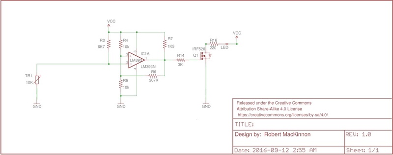
Basically the resistor divider created by R4/R5 and R9/R10 on the non-inverting input determines the set-point -- the voltage threshold where the MOS-FET turns on.  As the heat rises, the resistance of the NTC resistor decreases with temperature until the voltage at the inverting input is lower than set on the non-inverting input, and the MOS-FET turns on.  This will illuminate the LED and turn on the fans.  As the NTC resistor cools down, the set-point is reached again and the MOS-FET turns off.  The feedback resistors set a hysteresis where the turn-on temperature is higher than the turn-off temperature so that the output doesn't oscillate at the set-point.

The circuit you posted should also work but it lacks hysteresis.  You'd have to experiment (or model the circuit in LTSpice).  Remember that with the circuit I presented, you only need to build one side, not both.

R5 and R10 in the circuit I presented could be made adjustable so that the set-point could be dialled in.  As shown with the fixed resistors, the set-point is 100* F.


__________________________________________________
Robert
1987 K75 @k75retro.blogspot.ca
http://k75retro.blogspot.ca/
    

10Back to top Go down   temperature gauge Empty Re: temperature gauge Sat Oct 01, 2016 7:37 am

broberg

broberg
active member
active member
robmack wrote:
The circuit you posted should also work but it lacks hysteresis.  You'd have to experiment (or model the circuit in LTSpice).  Remember that with the circuit I presented, you only need to build one side, not both.

R5 and R10 in the circuit I presented could be made adjustable so that the set-point could be dialled in.  As shown with the fixed resistors, the set-point is 100* F.


Okey, so lets see If I got this right

temperature gauge Led-co10

The R6 is the resistor that makes sure there is some margin in the on/off function of the MOS-FET? Or is it the combination R6 and R7?
So it doesn't flicker when the resistance is at the set point value.


11Back to top Go down   temperature gauge Empty Re: temperature gauge Sat Oct 01, 2016 9:19 am

robmack

robmack
Life time member
Life time member
R6 = feedback resistor to ensure hysteresis
R7 = pull-up resistor
R14 = not really needed in your circuit because it forms part of the logical-OR circuit for two comparators

Otherwise, you got it.  Here are some points.

* In this circuit, Vcc is 12V (the motorcycle's battery voltage).  
* You can substitute almost any general purpose op-amp for the LM393 (TL071, LM741, LM358, etc.) if you want only one stage.  
* The current limiting resistor for the LED will not be needed if you use a 12V LED.  You will need to increase its value to 470-680 ohms if you attach a normal LED to Vcc; 220 is only if the LED supply voltage was 5V.
* you'll have to prototype this circuit and play with the values of R3 and R4/R5 so that it matches the characteristics of the temp sensor (i.e. an appropriate reference voltage for the set-point)


__________________________________________________
Robert
1987 K75 @k75retro.blogspot.ca
http://k75retro.blogspot.ca/
    

Sponsored content


View previous topic View next topic Back to top  Message [Page 1 of 1]

Permissions in this forum:
You cannot reply to topics in this forum